- Cams and followers transform rotary motion into precise, timed linear or oscillating movement.
- The design and classification of both cams and followers determine their function, efficiency, and application versatility.
- These mechanisms are crucial in internal combustion engines, automation, and a broad range of machinery.
- Proper understanding and design principles optimize durability, performance, and motion control.
Understanding cam and follower mechanisms is essential for students, engineers, and anyone involved with machinery and mechanical systems. These components play a pivotal role in converting rotary motion to linear or oscillating motion, powering everything from car engines to sewing machines. While often hidden behind the scenes, cams and their followers provide precise, repeatable movement, shaping the function of countless modern devices.
Despite their apparent simplicity, the theory behind cams and followers is rich with nuance and practical application. Designing these mechanisms requires an understanding of motion transformation, mechanics, geometry, and even material science. If you have ever been curious about how a car’s valves open and close at just the right moment, or how automated machinery achieves complex timed movement, this in-depth guide will provide you with all the insights you need into cams and followers.
What Is a Cam and Follower Mechanism?
A cam and follower system is a mechanism used to convert rotary motion into a predetermined reciprocating or oscillating movement. At its core, this mechanism consists of two main parts: the cam, typically the driving element that rotates or oscillates, and the follower, the driven component that responds to the cam’s profile by moving in a specific path. Both elements are mounted within a frame or guide, ensuring their motion is constrained and accurately directed.
The cam itself can be a disc, cylinder, or another shaped object, and its unique profile directly determines how the follower moves. The follower, often a rod or lever, maintains constant contact with the cam—sometimes through a spring, gravity, or mechanical constraint—to ensure the motion is faithfully transmitted. This setup can create a wide array of output motions, from simple linear reciprocation to more complex, timed oscillations.
Key Components of Cam and Follower Mechanisms
- Cam: The driving member, shaped to dictate the follower’s motion. Its profile design is crucial for determining the movement of the follower.
- Follower: The driven member, which translates or oscillates in response to the cam’s movement.
- Frame or Guide: The structural support that holds both cam and follower in position, often guiding the path of the follower.
The continuous contact between cam and follower is achieved via gravity, springs, or mechanical constraints like grooves or dual rollers. The choice between these constraint methods depends on the application and desired performance characteristics, such as reduced wear, noise, or precise timing.
How Does a Cam and Follower System Work?
When the cam rotates (or oscillates), its variable shape pushes the follower along a guided path. The follower’s movement depends on the cam’s profile. For example, in a radial cam, different radii along the cam’s edge will lift the follower up and down as the cam turns. This transformation allows a simple rotary input to trigger highly controlled reciprocating or oscillating output—essential for applications requiring accurate, timed movements.
A classic example is the operation of valves in internal combustion engines. As the camshaft turns, lobes on the shaft push against the followers, opening and closing valves at precise intervals to allow fuel/air intake and exhaust gas expulsion.
Classification of Cams and Followers
Cams and followers can be classified in several ways, based on their shapes, motion types, and the configuration of the mechanism. This variety allows engineers to select the right combination for each application, balancing space, load, noise, durability, and other factors.
Types of Cams by Shape
- Plate or Disc Cams (Radial Cams): These are flat plates or discs rotated around a fixed axis. The follower moves perpendicular to the cam’s axis, making these cams ideal for achieving up-and-down or back-and-forth follower motion. This is the most common type found in engines and machinery.
- Grooved or Slotted Cams: A variation of the plate cam, these have a groove cut into the surface of the disc. The follower rides inside the groove, which can provide positive constraint and eliminate the need for a spring or gravity to maintain contact.
- Cylindrical or Barrel Cams: Shaped like a cylinder with a groove cut into its outer or inner surface. The follower runs in this groove as the cylinder rotates, converting rotary movement into linear motion parallel to the axis. These cams are often used in machine tools and gear-cutting machines, especially where complex timing sequences are needed.
- Wedge Cams: These have a wedge-like shape and typically produce a sliding motion. The movement of the cam and follower is perpendicular to each other. Wedge cams are less common but provide linear movement in specific applications.
- Conjugate Cams (Dual Cams): Consist of two matching cam profiles working together, often used to achieve quiet, precise, and wear-resistant motion. These are advantageous where constant contact and minimal backlash are critical.
- Globoidal and Spherical Cams: These cams have curved (concave or convex) surfaces. Globoidal cams resemble cylinders but with a non-circular cross-section, while spherical cams provide a groove in a spherical surface. These types are used where complex, non-planar motion is required.
- End Cams: Feature a cam surface at the end of a rotating cylinder; rare due to manufacturing complexity and cost.
- Face Cams: The follower rides on the face (flat surface) of a rotating disk, often inside a slot. These are used for applications where the follower motion must be controlled precisely in one or more axes.
- Linear Cams: Instead of rotating, these cams move in a straight line. The profile is cut along the edge or surface. Examples include keys in pin-tumbler locks, where the linear movement of the key (the cam) lifts the pins (the followers) to the correct height.
Types of Followers by Contact Shape
- Knife-Edge Follower: Features a sharp edge at the tip, providing precise contact with the cam. However, this design causes rapid wear due to concentrated friction, so it’s rarely used in high-load applications.
- Roller Follower: Uses a rolling cylinder at the point of contact, dramatically reducing friction and wear. Roller followers are popular in high-speed and high-load environments, such as engine valve trains.
- Flat-Faced (Mushroom) Follower: The end is perfectly flat, allowing for smoother engagement with the cam. These are common where space is limited and are often used in automobile engines. To minimize wear, the axis of the follower may be slightly offset so that the flat face constantly rotates, distributing wear evenly.
- Spherical-Faced Follower: The end is convex (rounded), reducing contact stress and providing smoother action, especially helpful in high-speed or misaligned applications.
Types of Followers by Motion Path
- Radial (Inline) Follower: Moves along a path that passes directly through the cam’s center. Most standard cam and follower setups use a radial follower for straightforward motion transfer.
- Offset Follower: The axis of motion is displaced from the cam’s center. Offset can reduce side thrust, modify timing, or adjust motion characteristics.
Types of Followers by Movement Type
- Translating Follower: Moves strictly in a straight line (linear motion), either up and down or back and forth.
- Oscillating Follower: Pivots around a fixed axis, creating an angular or swinging motion in response to the cam. This setup is typical for systems that require angular displacement rather than pure translation.
Cam Mechanism Configurations and Modes of Operation
The relationship between cam and follower can be configured in several ways, affecting how input motion is transmitted and what output movement is achieved. Here’s a breakdown of common arrangements:
- Rotating Cam with Translating Follower: The cam rotates, causing the follower to move in a straight line. This is most often seen in plate or disc cam applications (like valve actuation).
- Rotating Cam with Oscillating Follower: The cam rotates and the follower swings on a pivot, producing an angular displacement. Used in textile machinery, printing presses, and more.
- Translating Cam with Translating Follower: Both cam and follower move in straight lines, often synchronized for specialized motion sequences.
- Stationary Cam with Rotating Follower: The cam remains fixed, while the follower system revolves around a shaft. These are less common and are mostly found in unique machinery or timing devices.
Follower Constraint Methods
Maintaining constant contact between the follower and cam is vital for reliable performance. Three primary methods ensure this constraint:
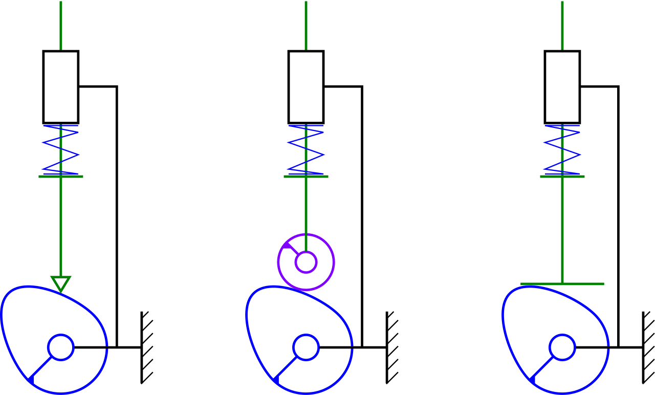
- Gravity Constraint: The weight of the follower is enough to keep it in contact with the cam. Simple, but only viable when speeds are low or follower mass is sufficient.
- Spring Constraint: A spring pushes or pulls the follower against the cam profile. This is the most common arrangement in high-speed machinery and automotive applications, where reliable contact is essential regardless of orientation or speed.
- Positive Mechanical Constraint: Mechanisms like grooves, dual rollers, or conjugate cams create a physical engagement that ensures contact at all times. This is crucial where backlash or lost motion must be minimized.
Essential Nomenclature and Key Terms
Understanding cam and follower theory requires familiarity with specific technical terms:
- Base Circle: The smallest circle that can be drawn tangent to the cam profile. This defines the minimum size of the cam and is fundamental to its geometry.
- Trace Point: A reference point on the follower (typically the knife-edge or roller center), used to generate the pitch curve as the cam rotates.
- Pitch Curve: The path traced by the trace point relative to the cam center as the mechanism operates.
- Working Curve: The actual surface of the cam in contact with the follower. For knife-edge followers, this matches the pitch curve; for roller followers, the working curve is offset.
- Pitch Circle: A circle from the cam center passing through the pitch points.
- Prime Circle (Reference Circle): The smallest circle drawn from the cam center to the pitch curve. For knife-edge and flat-faced followers, it matches the base circle; for roller followers, it’s larger by the roller radius.
- Pressure Angle: The angle between the follower’s motion direction and the normal to the pitch curve. High pressure angles can cause jamming or excess friction; keeping this angle within design limits is critical for smooth operation.
- Lift or Stroke: The maximum distance the follower travels from its lowest to highest position in a cam cycle.
- Pitch Point: The point on the pitch curve with the highest pressure angle.
- Displacement Diagram: A plot showing the follower’s position over a full cam rotation, depicting periods of rise, dwell, and return.
Motion Events: Rise, Dwell, and Return
One of the defining features of cam mechanisms is their ability to control periods of movement and rest (dwell) with high precision. Over a complete cam rotation, the follower typically experiences three sequential events:
- Rise: The follower moves away from the cam center. This is the upward or outward motion segment of the cycle.
- Dwell: The follower remains stationary despite continued cam rotation. This is critical in applications where the output needs to pause, such as keeping a valve open for a precise interval.
- Return: The follower moves back toward the cam center, usually mirroring the rise motion but in the opposite direction.
The displacement diagram illustrates these three phases—how far and how fast the follower moves during each segment. The precise shape of the cam profile determines the duration and speed of each event.
Follower Motion Profiles and Their Effects
The desired output of the follower can be achieved by tailoring the cam’s profile, using various mathematical curves to define the rise and return segments. Common motion profiles include:
- Constant Velocity: The follower moves at a uniform speed throughout the rise or return. While simple, this causes abrupt changes in acceleration at the start and end of motion, resulting in high forces and potential noise or wear. Rarely used in high-speed machinery.
- Constant Acceleration (Parabolic): Acceleration during rise or return is constant, resulting in smoother transitions and reduced maximum acceleration. This is favorable for minimizing shock and wear.
- Simple Harmonic Motion: The follower’s movement follows a sine wave-like curve—acceleration is smoothest at mid-stroke, with zero velocity at extreme positions. This profile is widely adopted for reducing noise and impact forces in high-speed engines.
- Polynomial or Custom Curves: Engineers may employ higher-order curves for very specific requirements, balancing smoothness, duration, and mechanical constraints.
OceanX: Exploration and Technology to Unveil the Ocean’s Mysteries
Design Principles for Cams and Followers
Designing a cam and follower mechanism involves choosing the correct cam profile to produce the desired follower motion. This requires careful consideration of geometry, material strength, pressure angles, and the specific application’s needs. Let’s break down the fundamental design steps and concepts:
Disk Cam with Knife-Edge Translating Follower
In this setup, a disk (plate) cam moves a knife-edge follower in a straight, reciprocating motion. The key design parameters include:
- Base Circle Radius (r₀): Defines the foundational geometry of the cam.
- Offset (e): The distance between the follower’s line of action and the cam’s center. Negative values indicate the follower is below the cam’s x-axis; offset can reduce side thrust or adjust timing.
- Follower Displacement (s): A function of cam rotation angle; it defines how far the follower moves at each cam position.
- Turning Direction (IW): Indicates clockwise (+1) or counterclockwise (-1) cam rotation, critical in determining the direction of motion and for geometric calculations.
A common design technique is inversion, where the cam is considered fixed and the follower moves around it, tracing the cam’s required profile as it undergoes its motion.
Disk Cam with Oscillating Knife-Edge Follower
For oscillating output, the follower pivots as the disk cam rotates. Design here involves:
- Distance Between Pivots (a): The length from the cam center to the follower’s pivot point.
- Follower Length (l): Distance from the pivot to the knife edge.
- Oscillating Angle (φ): The angular displacement of the follower relative to its starting position, as a function of cam rotation.
- Turning Direction and Position Parameters (IP, IW): Dictate positive-negative values for above/below axis and clockwise/counterclockwise movement.
Again, the inversion principle is applied to simplify profile design. The follower is imagined to swing through its required angles, tracing the cam’s shape, which can then be transposed back to the rotating cam in actual operation.
Disk Cam with Roller Follower
When using a roller follower, the profile design includes the radius of the roller as a key offset. The contact point (trace point) is at the roller’s center, so the cam’s profile is generated as an envelope of the roller as it rolls along the pitch curve.
- Roller Radius (r): Changes the effective pitch curve, requiring careful calculation to avoid interference or undercutting.
- Envelope Curve Parameters (IM, RM): Indicate whether the cam’s working curve is inside or outside the pitch curve, affecting the final cam shape.
Profile generation for roller followers involves two steps: calculate the pitch curve using the inversion method, then determine the actual cam profile as the locus of points tangent to the roller as it moves along the pitch curve.
Pros and Cons of Cam and Follower Mechanisms
Cam and follower systems offer unique advantages but are not without drawbacks. Here’s a balanced view:
- Advantages:
- Simple mechanism for converting rotary motion to reciprocating or oscillating movement.
- Highly customizable output motion; almost any desired follower path can be achieved with proper cam design.
- Capable of accurate and repeatable motion, especially necessary in timed or automated systems.
- The mechanism can withstand significant vibration and dynamic loads, making it suitable for engines and high-speed machinery.
- Versatile—found in a vast range of mechanical applications.
- Disadvantages:
- Cams are prone to wear and tear, particularly at the contact surface, requiring precise manufacturing and good lubrication.
- Complex cam profiles can be difficult and costly to produce, especially for high-performance or custom-designed mechanisms.
- The system occupies more physical space compared to simpler linkages.
- High surface stresses can arise, particularly in high-speed applications, necessitating durable materials and careful design.
Industrial and Everyday Applications of Cam and Follower Mechanisms
You may not realize it, but cam and follower systems are at the heart of many devices you use daily and are essential in industrial processes. Here are some prominent applications:
- Internal Combustion Engines: The quintessential application. The camshaft uses specially shaped lobes to open and close intake and exhaust valves with impeccable timing, allowing the engine to breathe correctly for optimal performance.
- Automatic Machinery: In lathes, looms, textile machinery, paper-cutting machines, and more, cams time the movement of parts, automate tool changes, and control complex processes.
- Consumer Devices: Cam and follower systems move needles in sewing machines, create motion in toys (such as animating figures), and control the operation of dishwashers and washing machines (through cam timers).
- Clocks and Timing Mechanisms: Cams are used to advance dials, activate chimes, and coordinate day/night functions in mechanical clocks.
- Automotive Transmissions: Shift control barrels (cylindrical cams) manage gear selection in sequential transmissions, such as those found in motorcycles.
- Security Devices: Linear cams act as the control surface in pin-tumbler locks; the shape of the key (the cam) sets the pins (followers) to the correct position.
- Mechanical Computers and Analog Devices: Before digital controllers, cams encoded complex mathematical functions and control sequences, enabling automation and computation through purely mechanical means.
Historical Perspective and Evolution
The roots of cam mechanisms stretch back centuries, with notable examples in ancient China and the Middle East. Early cam-like devices appeared in crossbow triggers and water-driven machines. By the Middle Ages, cams were integral to automata and timekeeping devices. Over the centuries, their use expanded with industrialization, evolving into the complex, high-performance systems seen in modern automotive and manufacturing technology.
The versatility and reliability of cam and follower mechanisms have ensured their continued relevance even as electronics and digital controls replace many mechanical systems. In areas requiring pure mechanical motion conversion, precise timing, or high durability, the cam and follower remain indispensable.
Contemporary Developments and Research
While the fundamental theory of cam and follower mechanisms has remained constant, modern engineering continues to refine their design and application. Computer-aided design now enables highly complex cam profiles to be generated, manufactured, and analyzed with high precision. Advanced materials and new manufacturing techniques improve durability, reduce friction, and enable lighter, more efficient mechanisms.
Researchers and engineers are continually seeking to maximize the efficiency, minimize the wear, and extend the lifespan of cam systems—especially in high-speed, high-load contexts like engines and automated manufacturing.
Cam and follower mechanisms offer an extraordinary blend of simplicity and versatility. They are the silent workhorses converting rotary inputs into timed, linear, or oscillating actions throughout modern industry and daily life. Through careful design, these mechanisms can deliver smooth, repeatable, and highly controlled movement in everything from a child’s toy to the valve train inside a Formula 1 engine. Whether you are an engineering student, an aspiring designer, or someone simply curious about the mechanics behind the machines we depend on, delving into cam and follower theory provides a fascinating look at the intersection of geometry, physics, and practical invention.