
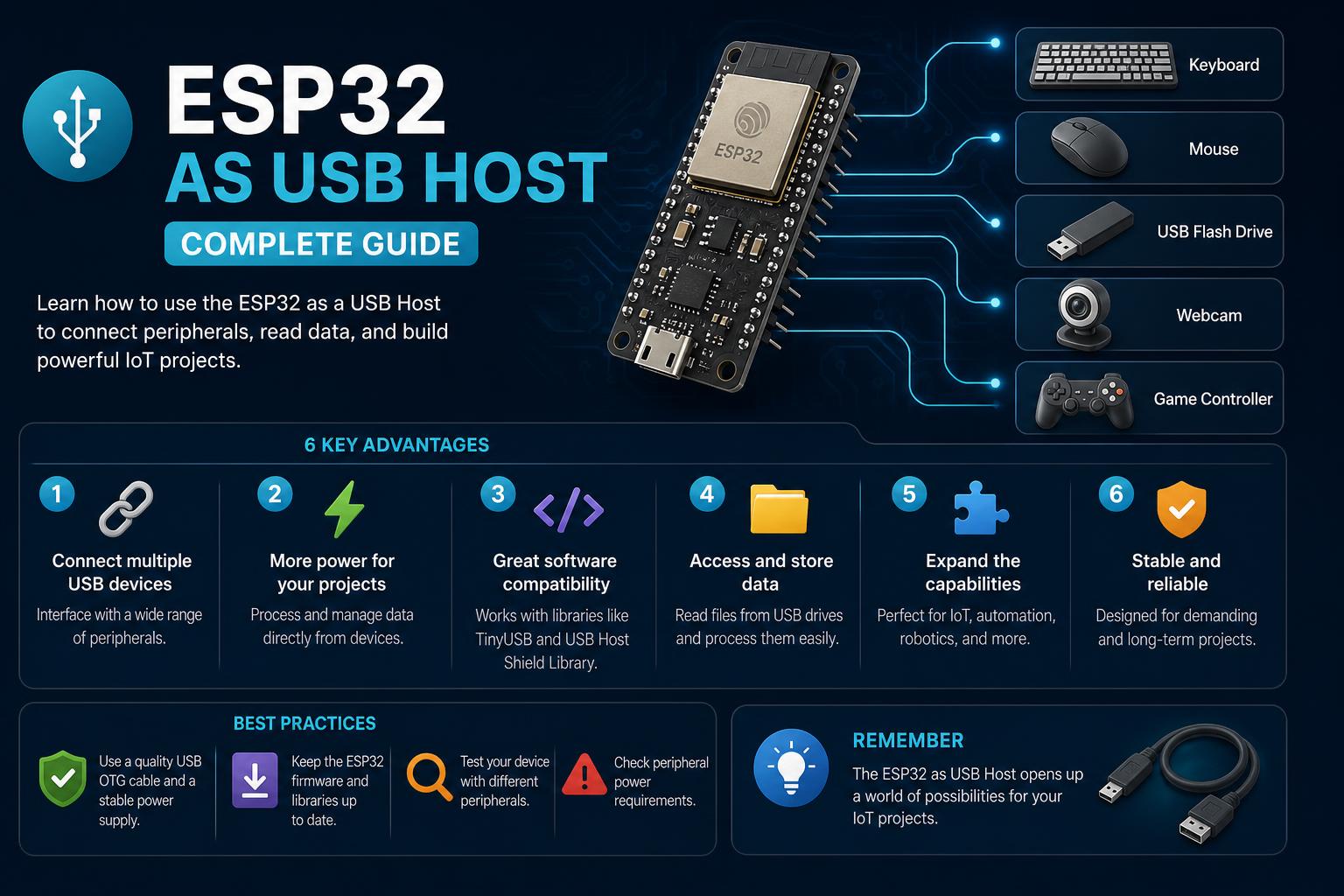
- ESP32-S3 and S2 provide native USB host support with dedicated hardware and robust API stacks, empowering direct connection to a wide variety of peripherals.
- Successful USB host operation on ESP32 boards depends on careful attention to power delivery (VBUS), accurate wiring/connection of data lines, and correct software library configuration.
- Community-driven libraries, wrappers, and in-depth board documentation are instrumental in overcoming hardware quirks, maximizing compatibility, and ensuring reliable enumeration of devices.
In the dynamic world of microcontrollers and edge device projects, the ESP32 family has steadily gained popularity, particularly with the evolution of USB host capabilities. Whether you’re an enthusiast eager to connect Human Interface Devices (HID) like keyboards and mice, or a developer exploring mass storage and communication gadgets, understanding how to harness the ESP32 (especially the S2 and S3 models) as a USB host is more relevant than ever. With new board layouts, firmware libraries, and practical wiring methods, your options for implementing smart, interactive hardware solutions continue to expand rapidly.
Yet, as accessible as this landscape might sound, setting up an ESP32 as a USB host reveals a web of technical considerations—ranging from power management and pin configuration, to the nuanced differences across board revisions and host stack implementations. Let’s cut through the jargon and walk you through how ESP32 boards unlock USB host mode, what hardware support exists, and which libraries and real-life examples will put your next project on solid ground.
Understanding ESP32 USB Host Capabilities
The ESP32-S2 and ESP32-S3 chips are designed with native USB-OTG (On-The-Go) support. This means they can act as both device (slave) and host (master). USB host functionality enables the direct connection and control of USB peripherals such as keyboards, mice, mass storage devices, and more, a leap forward in embedded versatility compared to basic UART or SPI-based communication modules.
The implementation of USB Host mode on ESP32 hinges on two core factors:
- Physical Connectivity and Board Layout: Not all development boards enable true USB Host capabilities from the get-go. Many require additional wiring or board modifications to supply and switch 5V power to the connected device via VBUS.
- Software and Library Stack: Espressif provides a powerful set of USB host APIs (through ESP-IDF) and examples, with Arduino and third-party wrappers adapting these APIs for more familiar ecosystems.
ESP32-S3 and ESP32-S2: The Real USB Hosts
The ESP32-S3 and ESP32-S2 chips are the main players here. They incorporate dedicated USB hardware that supports both host and device modes at full and low speeds. S3 introduces improved performance and more reliable host operation.
Example Boards: The ESP32-S3-USB-OTG dev kit stands out with onboard USB Type-A host and device ports, a USB interface switch, LCD display, and built-in current control circuits, all tailored for USB host experiments. Similarly, the XIAO ESP32-S3 board, from Seeed Studio, provides accessible USB-C connectivity, but—as we’ll detail later—requires smart hardware routing to fully exploit host mode.
Physical and Electrical Design: Making USB Host Work
Many hurdles encountered by beginners stem not from code but from hardware configuration and power delivery requirements.
Powering the USB Host Port (VBUS)
When you switch an ESP32 board to host mode, your microcontroller must deliver 5V power to the VBUS line for the USB device (e.g., keyboard, mouse) to enumerate and operate. If the board is not designed to forward 5V correctly, your device will be invisible to the ESP32 no matter how clever your code is.
On ESP32-S3 dev kits, you often find a solder jumper or pad (e.g., labeled USB-OTG) that, when bridged, routes the 5V line from the board’s power supply to the external USB host port. Care is needed: if you plug both USB ‘COM’ (programming/power/debug) and USB ‘HOST’ into a PC simultaneously, you may create a dangerous back-feed situation. Only connect both if you have properly isolated or disconnected the jumper as advised in your board’s manual.
Boards like the XIAO ESP32-S3 require external supply via powered hubs or a careful wiring of the board’s 5V output to the host port. Users report that lack of VBUS power is the main reason for failed host device enumeration—so make this your first troubleshooting step.
Switching Data Lines and Ports
Advanced board designs may include a USB switch IC, controlled by a GPIO (e.g., USB_SEL), which toggles USB data lines (D+, D-) between device and host roles. Refer to your board’s schematic or documentation for details—wrongly set switches or wrong port selection will also prevent USB host functionality.
- For ESP32 S3-USB-OTG boards, GPIO18 is used to switch modes. High enables host, low enables device.
- On XIAO, you must use a secondary USB connector—sharing a single port is possible only with external switches or hubs.
Hint: For straightforward prototyping, it’s wise to select a dev kit with clearly segregated host and device ports, onboard 5V supply, and detailed pin breakout.
ESP32 USB Host Stack: Software Layers and APIs
Espressif’s ESP-IDF framework ships with a full USB Host Stack. It’s a comprehensive, event-driven C library that exposes lower APIs for custom host class drivers but also ships with out-of-the-box support for popular peripheral types. For makers preferring Arduino, wrappers and third-party libraries bridge the gap, making USB host access more familiar and less intimidating.
Key Features and Limitations (ESP-IDF)
- Full support for Full-Speed (FS) and Low-Speed (LS) USB devices
- All transfer types: Control, Bulk, Interrupt, Isochronous
- Multiple class drivers: allows several device types to run concurrently
- Global suspend/resume supported, including auto-suspend mode
- Software event-driven architecture: programmers must actively poll or handle library and client events
Current limitations: Only asynchronous transfers and a single configuration per device are supported. OTA firmware upgrades, transfer timeouts, and manual power management can require advanced handling or are not available yet.
Host Library Architecture
ESP-IDF splits the logic among:
- Host Library (lowest API layer, handles USB events and device enumeration)
- Host Class Drivers (add application-specific communication logic for CDC-ACM, HID, MSC, etc.)
- Client Tasks (where the application’s USB control flows)
- Daemon Task (centralizes event processing)
Programmers must create client and daemon tasks, repeatedly calling event handler functions such as usb_host_lib_handle_events() and usb_host_client_handle_events(). These ensure enumeration, connection, transfer, and disconnection events flow correctly through your application.
[relacionado url=”https://www.ikkaro.net/what-is-arduino-iot-cloud-hub-the-ultimate-guide-for-modern-iot-projects/”]
Supported USB Classes and Example Projects
Espressif provides class driver examples for:
- CDC-ACM (Virtual Serial Communication, e.g., USB modems and serial dongles)
- MSC (Mass Storage Class – USB thumb drives, SD cards)
- HID (Human Interface Devices, including keyboards, mice, joysticks)
- UVC (USB Video Class, e.g. webcams – announced but less mature for S3/S2)
The library comes with API headers (like usb/usb_host.h) and helper functions for parsing USB descriptors and handling standard USB requests. API documentation and examples are thorough, but require some embedded C proficiency to adapt to custom scenarios.
HID Devices: Keyboards and Mice on ESP32
For most practical projects, connecting a USB keyboard or mouse to control an embedded device is a major use case. Espressif’s USB Host HID driver implements this out-of-the-box—see the official documentation for the HID host sample.
Arduino users, meanwhile, benefit from wrapper libraries. For instance:
- ESP32_USB_Host_HID: A library built on Espressif’s host stack, specifically designed for HID keyboards and mice—compatible with ESP32-S3 and programmable via Arduino.
- tobozo/ESP32-USB-Soft-Host: An Arduino wrapper relying on a software-based USB host stack for low-speed devices, making it possible to use even on ESP32 variants without native USB peripherals (some hardware limitations apply, described below).
Practical Example: ESP32-S3-DevkitC & PlatformIO Integration
One community member described compiling an example HID host sketch directly with PlatformIO using the Arduino-ESP32 3.3.1 core. Their board (ESP32-S3-DevkitC-N16R8) sports two USB-C ports, separating programming/debugging (via USB-to-UART) and the S3’s native USB pins.
- After connecting the appropriate USB-OTG jumper/pad to enable VBUS, they attached a USB-C to USB-A OTG adapter to the host port and successfully received keystrokes from a plugged-in keyboard in the serial monitor.
Warning: Using both ‘COM’ and ‘USB’ ports simultaneously is hazardous unless properly isolated. Remove the solder link (or switch it off) before reprogramming or switching between host and device modes.
XIAO ESP32-S3: The DIYer’s Route to Reliable USB Host
The Seeed Studio XIAO ESP32-S3 illustrates the quirky realities of small-form factor boards. Out of the box, its single USB-C port acts as a device—for programming and debugging—but not host. Users are advised to:
- Leave the USB-C port for programming only.
- Wire runtime UART debug to D6/D7 (GPIO43/44) and connect them to a cheap USB-UART dongle for monitoring.
- Wire a separate USB host connector (USB-A or USB-C breakout) directly to the S3’s USB D+ (GPIO20) and D- (GPIO19) pins—preferably through a USB 2.0 switch if available.
- Crucially, provide 5V VBUS externally—most issues arise from missing VBUS. A powered USB hub or an external 5V switch is a sound solution.
For HID (keyboard) demos, the recommended wiring results in reliable device detection and allows people to observe key events over UART at 115200 baud, all while running a classic blinky demo via GPIO21. Wiring diagrams and code samples can be found on relevant community threads and Seeed Studio forums.
Alternative Software: Software-Driven USB Host (LS)
The ESP32-USB-Soft-Host project provides a pure software implementation of a USB low-speed host on ESP32, essentially bit-banging the protocol through general I/O pins. This enables limited host support even for ESP32 variants without true USB hardware, but it comes with caveats:
- This solution supports up to four HID low-speed devices concurrently (e.g., basic mice and keyboards).
- Performance and compatibility may vary—some mice perform flawlessly (e.g., LogiLink, Microsoft), others need resets, and power-hungry devices may need external 5V supply.
- Reliability drops on boards where IO pins overlap with PSRAM or where timings cannot be respected (as seen with some gaming mice).
The documentation provides a compatibility matrix and connection tips—if attempting on a non-S2/S3 variant, this is your main option, but proceed with realistic expectations. Full details, including tested models, are on the .
Exploring Board-Level Design: ESP32-S3-USB-OTG in Depth
The ESP32-S3-USB-OTG dev board is specifically engineered for host/peripheral development and application prototyping. Here is what sets it apart:
- Dedicated USB Type-A host and device connectors, with a USB interface switch controlled by a switch IC and GPIO.
- Multiple power supply options: via Micro-USB (for board only), USB-DEV (for powering the USB-HOST interface and charging batteries), or via an add-on 3.7–4.2 V lithium battery (boosted to 5V for host mode).
- Current limiting and monitoring: Onboard MIC2005A provides a safe 500 mA supply limit, with current monitoring and enable pins for fail-safe operation.
- Fully documented function pinout: GPIO18 for mode switching, GPIO13 for boost enable, GPIO17 for current limit enable, etc.
- Additional peripherals: 1.3” LCD (SPI), SD card slot (SDIO/SPI), multiple user LEDs, accessible boot and reset buttons.
This level of integration makes the S3-USB-OTG a practical choice for in-depth USB experimentation: powering different devices, switching between modes via software, monitoring voltages and current, and developing custom user interfaces (with the integrated LCD) or logging storage (via SD card).
Practical Steps: Setting Up Your Own ESP32 as a USB Host
The workflow for connecting and using USB devices with an ESP32 is broadly as follows:
- Board Selection & Preparation: Choose a board with host-capable pins; study its schematic for VBUS control, port selection, and jumper settings if applicable.
- Power Management: Ensure the host port receives 5V VBUS—bridge jumpers, use powered hubs, or wire external 5V sources as required. Watch for current limits (500 mA typical maximum per port).
- USB Port Selection: Configure the USB switch (if available) to select between device and host; verify which GPIOs control the switching, and confirm your wiring before powering on.
- Firmware & Libraries: Use ESP-IDF’s USB host stack, or install suitable Arduino libraries (e.g., Stepper motor control as an example of device control), to adapt examples before diving into application-specific code.
- Monitoring & Debugging: If your board’s only USB port is in host mode, redirect debugging and serial output to hardware UARTs accessible via TX/RX pins and a USB-UART dongle.
- Testing Peripherals: Start with basic HID devices—most keyboards and mice should enumerate without issues if power is present and wiring is correct. Monitor output for device events and report errors.
Pro tip: If you’re not seeing device events, double-check power. Most USB failures on ESP32 in host mode happen because the target device doesn’t actually receive 5V VBUS, not because of faulty firmware!
Advanced Configuration: Enumerating Multiple Devices and Handling Hubs
The host stack supports onboard hub(s), enabling connection of multiple devices through hub hardware, if enabled in the configuration and available in the hardware design.
- Enable hub support by setting relevant options (e.g., CONFIG_USB_HOST_HUBS_SUPPORTED for single, CONFIG_USB_HOST_HUB_MULTI_LEVEL for multiple hubs).
- Enumeration delays and power-up sequencing can be customized to accommodate quirky or non-compliant devices (using debounce and recovery interval settings).
Careful software control is needed to manage bus suspend/resume cycles, transfer timeouts, and multiple device interfaces. Generally, ESP-IDF offers a flexible but developer-intensive platform—meaning the more devices you plan to juggle, the more you’ll rely on callbacks and custom event loops.
[relacionado url=”https://www.ikkaro.net/stepper-motor-control/”]
Non-Standard and Legacy Devices: Enumeration Filters and Custom Drivers
For devices with multiple configurations, or those requiring specific enumeration logic (filtering, configuration selection), the host stack provides a usb_host_enum_filter_cb_t callback. Enable CONFIG_USB_HOST_ENABLE_ENUM_FILTER_CALLBACK in menuconfig to hook custom logic. This allows developers to build robust applications able to interact with devices that don’t perfectly conform to the standard enumeration process.
For non-standard USB communication devices or unique gadgets, you can build a class driver from scratch atop the host library, or extend provided examples to claim interfaces, submit and receive transfers, and handle class-specific requests (see for more information).
Board and Project Options: Going Beyond the Basics
Some developers look to combine USB host features with additional capabilities: use the ESP32 as a Wi-Fi USB gateway, combine mass storage with LCD GUIs, or create complex power management setups (e.g., switching between USB-DEV and battery boost supplies).
- The S3-USB-OTG board showcases integration: all major control signals (mode switching, current limits, and power source selects) are accessible via GPIOs, making programmatic switching and monitoring straightforward.
- For boards without these features, creative soldering and add-on circuitry (such as USB switch ICs, powered hubs, or voltage regulators) become part of the adventure.
Advanced projects may also exploit the built-in SD card interface (for mass storage logging), SPI LCDs (for live feedback), and extensive GPIO breakouts for combining user input, sensors, and actuators with the USB host capabilities.
Challenges and Community Wisdom
Across forums and project repositories, a recurring theme emerges: physical setup and power delivery are responsible for the vast majority of USB host issues on ESP32 boards. From soldering jumpers to aligning UART debug lines, early-stage problems are best solved by referencing your board’s hardware documentation, double-checking all wiring, and ensuring that your USB peripherals (especially keyboards and mice) receive consistent VBUS power.
Community projects and wrappers (notably and ) have sprung up to streamline these experiments, wrapping lower-level ESP-IDF calls into accessible Arduino classes and providing practical examples for debugging and extending USB host features.
Real-World Device Support and Reliability
Compatibility varies by device class and model. Most classic wired keyboards, standard mice, and basic flash drives pose no problem for the ESP32-S3/S2 and their offshoot dev kits, as long as the above electric and firmware caveats are heeded.
For less compliant or finicky devices (especially gaming mice, gadgets with extra features, or those requiring more than 500 mA), success rates are mixed and may require firmware tweaks, repeated resets, or powered hubs. Community-maintained device matrices and GitHub issues are a great place to check before committing to large-scale deployment. HID wrappers allow logging of vendor/product IDs and connection events, aiding compatibility research.
The Future of ESP32 USB Host: Trends and Opportunities
With the maturation of Espressif’s USB host stack, expanded hardware offerings, and growing ecosystem of wrappers and user-contributed guides, developing robust USB host solutions on the ESP32 platform is more accessible than ever. Expect further improvements in supported transfer types, power management, and higher-level libraries as the community experiments further and the manufacturer continues to release firmware updates and documentation improvements.
Transforming your ESP32 into a full-fledged USB host involves both hardware and software considerations, but with a solid development kit, proper wiring, and community support, you will soon be powering and controlling keyboards, mice, and a variety of other peripherals with ease.