
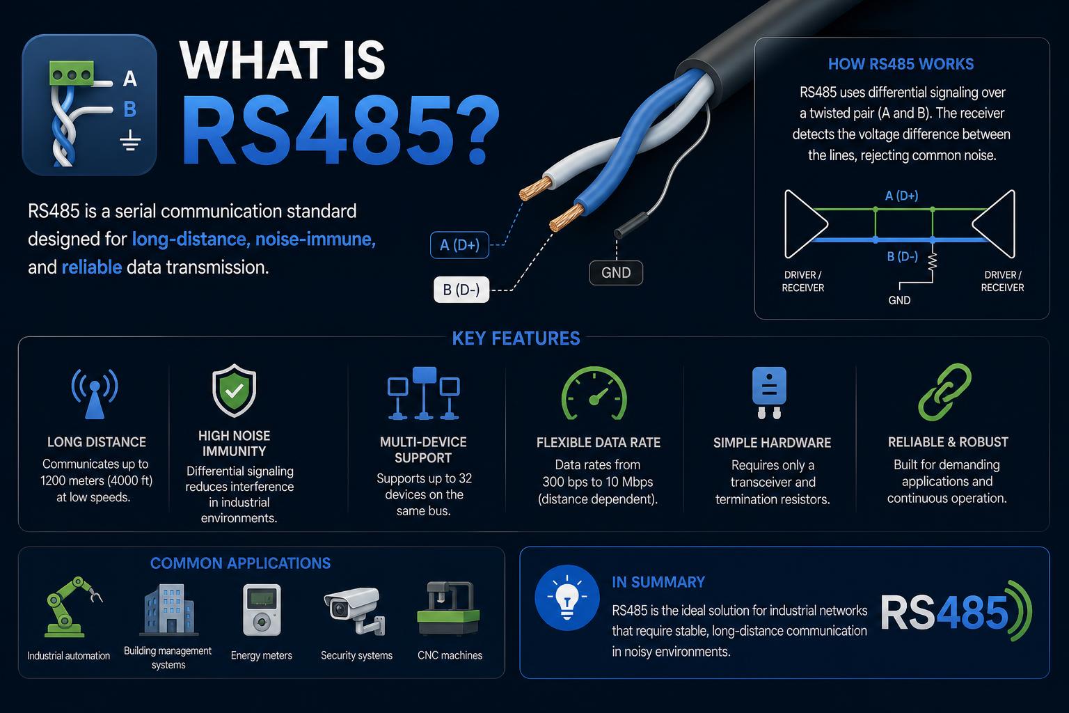
- RS-485 enables noise-resistant, long-distance serial communication in industrial and building automation.
- Proper bus wiring, termination, and protocol selection are essential to reliable RS-485 networks.
- RS-485's flexibility supports a variety of topologies and multiple protocols like Modbus or proprietary solutions.
In the world of modern industrial communication, understanding the right interface for reliable device networking is essential. RS-485, often mentioned alongside other serial standards, stands as one of the most robust solutions for connecting industrial devices across long distances, even in environments plagued by electrical noise and interference. Its unique electrical and wiring features, flexibility for supporting multiple devices, and adaptability in various industries make it a mainstay for automation, manufacturing control, building management, and beyond.
Diving into the essentials and complexities of RS-485 is crucial for anyone dealing with serial communications and industrial automation. Whether you’re an engineer setting up a motion controller, a facility manager implementing smart building controls, or just a tech enthusiast exploring the backbone of digital device networks, this article will clarify everything you need to know about RS-485 – from its theoretical foundation to wiring recommendations, protocol usage, practical applications, and expert best practices. If you’re looking for the most detailed, approachable, and practically useful guide, you’ve landed in the right place.
Unraveling RS-485: What Sets It Apart?
RS-485 is a hardware specification that strictly defines the electrical characteristics for transmitters and receivers, laying the groundwork for reliable serial communications without prescribing any specific communication protocol. Unlike some older standards, its focus is entirely on how data electrically travels between devices—leaving the actual language of communication, such as Modbus or ASCII, for protocol layers built on top.
The magic of RS-485 lies in its balanced differential signaling. Two wires, typically labeled ‘A’ and ‘B’, work together: when one wire goes high, the other goes low. This opposition ensures that even if both wires pick up noise from the environment, the receiver only pays attention to the voltage difference between the lines, not their absolute levels. This design makes RS-485 communication far more resistant to the kinds of electrical interference common in industrial environments.
Supporting both point-to-point and multipoint (multi-drop) topologies, RS-485 changes the game for industrial networking. Unlike RS-232, which could only handle a single connection, RS-485 lets you hook up to 32 devices (and with modern ICs, sometimes more) along the same pair of wires, slashing cabling costs and complexity.
Origins, Nomenclature, and Standard Details
RS-485 emerged in the 1980s as a step forward from prior standards like RS-232 and RS-422, addressing critical shortcomings in range, speed, and noise immunity. Officially, RS-485 is now known as TIA-485 or EIA-485 after organizational changes in the governing bodies, but ‘RS-485’ remains the most widely used designation in industry documentation and conversation.
The standard only formalizes the physical layer. It details electrical aspects such as the necessary differential voltages, required noise immunity, and operational voltage ranges for both transmitters and receivers:
- Minimum differential voltage: +/- 200 mV at the receiver, which provides a robust margin for signal detection even over degraded or long cables.
- Typical voltage ranges: Devices can tolerate anywhere from -7 V to +12 V between A and B, so mixed-voltage networks are feasible within this envelope.
- Logic states: If Line A is negative relative to B, the system interprets this as a logic 1 (also known as ‘mark’). The inverse (A positive to B) means logic 0 (‘space’). This can be a source of confusion, so always check vendor datasheets, especially regarding label polarities.
RS-485 does not specify any wiring connector, leaving engineers free to use any suitable method such as screw terminals, D-sub connectors, or special industrial plug types.
The Physical Layer: Cables, Wiring, and Network Topology
A hallmark of RS-485 is its support for long-distance, high-speed data transfer using nothing more than a basic twisted pair cable. At slower speeds, cable runs can extend up to 1,200 meters (around 4,000 feet), making it perfect for sprawling factories or distributed sensor networks.
Twisted pair cabling is crucial. By twisting the two conductors together, external interference couples equally to both, which the differential receiver then subtracts out. Some installations also use shielding for additional noise reduction.
Wiring Topology Choices
The recommended RS-485 network takes a daisy-chain (linear bus) form. Devices are connected one after the other, with the critical rule being that the main communication line should be kept continuous, and ‘stubs’—branches off the main line—should be as short as possible (ideally, just a few centimeters). This layout:
- Ensures signal integrity by minimizing reflected or distorted signals.
- Can easily support tens of devices per standard, and potentially more with modern hardware.
Star and ring topologies are generally discouraged because they increase the risk of signal reflections, which can corrupt data – though specialized repeaters can be used if physical constraints demand such layouts.
Termination and Biasing
Proper termination is critical for any RS-485 network to prevent data errors. At each physical end of the cable, a resistor (typically matching the cable’s characteristic impedance, e.g., 120 ohms) bridges the A and B wires. This termination:
- Absorbs the transmitted signal, preventing it from bouncing back and causing destructive interference.
- Lowers susceptibility to electrical noise.
Biasing resistors are also used (often pull-up and pull-down) to ensure the lines don’t float and inadvertently interpret ambient noise as a valid binary state when no device is actively transmitting.
Half-Duplex vs. Full-Duplex: Communication Modes
Most RS-485 installations use half-duplex communication with two wires. In this arrangement, data transmission occurs in both directions but only one device can speak at a time. Devices listen on the line and only engage when prompted, as determined by higher-level protocols.
Full-duplex is possible by using four wires (two pairs), but this is uncommon given the added complexity and the primary advantages of bus topologies in industrial contexts.
Electrical Robustness: Immunity to Noise and Flexible Voltage
RS-485’s differential signaling underpins its ruggedness. In noisy environments—such as manufacturing lines with motors, welding equipment, or high-voltage controls—cable runs can pick up stray voltages. Since both wires in the twisted pair receive nearly identical interference, the differential receiver subtracts one from the other, effectively canceling out external noise. This property, called “common mode rejection”, is a primary reason RS-485 is chosen for industrial and automation applications.
RS-485 does not mandate a fixed bus voltage but rather the minimum voltage difference necessary for correct operation. Any compliant device must tolerate the standard’s broad voltage window. This lets engineers design custom solutions, often leveraging the existing board voltages (anywhere in the -7 to +12 V range), streamlining hardware integration and reducing design complexity.
Layering Protocols: From Physical to Application Layer
RS-485’s flexibility is both an asset and a consideration, as it does not specify a communication protocol (speed, timing, data format, addressing) but merely the method of electrical data transfer. Higher-level protocols such as Modbus (especially Modbus RTU), ASCII, Profibus, and proprietary variants are often layered atop RS-485. Here’s a quick breakdown of how the Open Systems Interconnection (OSI) model applies:
Physical Layer
Handles the raw electrical transfer of data. This is the only layer RS-485 standardizes.
Data Link Layer
Defines aspects like addressing, error checking, and organizing transmissions. Most industrial control applications use a UART (Universal Asynchronous Receiver/Transmitter) to packetize data over RS-485.
Half-duplex operation is typical: the host device asserts control, issues commands, and target devices listen and respond by taking control in turn. In combination with a UART, the system can manage full-duplex or simplex formats if desired, by adjusting wiring or hardware operation.
Network and Application Layers
Focus on communication details—how devices are identified, how messages are constructed and interpreted, and how the system as a whole is managed. RS-485’s openness allows for everything from highly robust, standardized protocols (like Modbus, see Modbus official site) to streamlined, application-specific command sets for extreme speed or device simplicity.
Comparing RS-485 to RS-232 and RS-422: Why Choose RS-485?
Many engineers (and internet guides) compare RS-485 to the ubiquitous RS-232 interface. Let’s clarify the distinctions:
- Device Count: RS-232 supports only one transmitter-receiver pair per link, while RS-485 can host up to 32 (sometimes more) devices per bus.
- Cable Length: RS-232 tops out around 15 meters (50 feet), but RS-485 stretches up to 1,200 meters (4000 feet), even at reasonable data rates. This makes it ideal for large installations or distributed sensor networks.
- Noise Immunity: Differential signaling and robust voltage thresholds ensure much higher resistance to electrical interference in RS-485 systems.
- Data Rate: At short distances, RS-485 can handle data speeds up to 10 Mbps and, under optimal conditions, even higher.
- Wiring and Connectors: RS-232 often uses standardized connectors (like DB-9), while RS-485 lets you choose, often relying on industrial screw terminals, D-subs, or custom blocks.
For those interested in more about how what is UART and its role in RS-485 communication, exploring hardware design can provide valuable insights.
Real-World Topologies and Wiring Examples
The classic RS-485 wiring approach is the daisy-chain or bus topology, where each device’s A+ and B- lines simply continue to the next device. Ideally, connection stubs are avoided. If a stub is required to connect a device, keep it as short as physically possible; excessive length leads to unwanted signal reflections and potential communication errors.
The entire bus is anchored at each end by a termination resistor, typically 120 ohms, matching the cable’s characteristic impedance.
As seen in installations like the LORRIC paddle wheel flowmeter system, the network connects a variety of distributed field devices (such as flowmeters, sensors, or actuators) to a central PLC (Programmable Logic Controller) for data aggregation, control, and monitoring. This backbone enables everything from smart water dispensing in chemical plants to real-time monitoring of environmental conditions across multiple remote nodes.
Common Application Protocols and Practical Uses
Since the RS-485 standard defines only physical connection, the “language” devices use is determined by higher-level protocols or custom packet formats. Commonly adopted options include:
- Modbus RTU: The most widespread open protocol, especially for PLCs, sensors, flowmeters, and distributed I/O. It defines polling, addressing, and message structure for reliable communication.
- ASCII: Used for simpler setups and direct device interaction.
- Profibus: A powerful proprietary protocol employed in high-end industrial automation networks.
- DMX512: In theater, live event lighting, and effects, RS-485’s physical layer is used by the DMX protocol to broadcast precision lighting control data.
For detailed protocol implementation and compatibility, consult the .
Other fields of adoption include SCSI-2 and SCSI-3 hard disk communications, in-flight entertainment and control systems, audio signal distribution (AES3), and more. Because the electrical layer tolerates so much noise and allows for flexible wiring, building automation, security access control, and remote serial devices (like model railway control) all rely on RS-485 bus architecture.
Devices from leading automation brands and sensor manufacturers, such as flowmeters, weather stations, temperature/humidity sensors, and motion encoders (see Same Sky’s absolute encoders with RS-485), typically use RS-485 to guarantee reliable readings and commands even in electrically unreliable environments. Manufacturers like LORRIC and RealPars illustrate how critical robust bus wiring is for smooth automation in both chemical process control and fault-tolerant remote device management.
Practical Implementations & Case Studies
Case Example: Industrial Chemical Dispensing in Semiconductor Manufacturing
At Hingsen Semiconductor in China, the central chemical dosing and dispensing system leverages RS-485 to network multiple valve boxes and flowmeters. Each process point is equipped with a sensor (such as LORRIC’s paddle wheel flowmeter) that communicates real-time flow measurements directly to the facility’s central control system over RS-485. As soon as the desired amount of reagent is dispensed, the central system—via the RS-485 network—halts the process seamlessly. This not only enhances precision and safety but also allows for rapid reconfiguration and expansion of the physical layout.
Automation in Manufacturing and Motor Controls
RS-485 is prevalent in distributed control systems where multiple devices—like PLCs, Variable Frequency Drives (VFDs), and HMIs (Human-Machine Interfaces)—communicate over robust, long-distance networks. This setup enables centralized monitoring and control of processes such as water pumping and automated motion, allowing operators to remotely tweak parameters, monitor conditions, and manage maintenance all from a single control center.
Building Automation and Security
Remote sensors and controllers for lighting, climate, and security widely use RS-485 thanks to its ability to support many devices over lengthy cables. Building management systems can tie together climate sensors, access control points, cameras, and alarm modules into a unified network, slashing wiring costs and boosting system reliability.
Best Practices in Network Design, Commissioning, and Troubleshooting
Attaining optimal performance with RS-485 isn’t just about following the standard—it’s about practical implementation, too. Here are the most crucial hands-on guidelines:
- Termination Resistors: Always place a resistor at each end of the main cable to suppress reflection and maintain signal clarity, especially for high-speed or long runs.
- Keep Stubs Short: Any branch from the main line (connecting to a device) should be minimized to avoid signal degradation. If unavoidable, use repeaters or network redesign.
- Correct Shielding and Grounding: Use shielded twisted pair cables when possible. Ground the shield at a single point to prevent ground loops, and keep the reference (SC/GND) consistent throughout the run.
- Biasing for Idle States: Pull-up and pull-down resistors can ensure that when no device is transmitting, noise doesn’t masquerade as valid data. This is particularly important in networks with lots of devices or frequent device shutdowns.
- Check Device Ratings: Ensure all hardware, including transceivers and wiring, can tolerate the full voltage and load range expected for your configuration. This is especially relevant for mixed-voltage environments or brands.
- Monitor Protocol Traffic: Use protocol analyzers or serial sniffers to diagnose communication faults, especially when layering higher protocols like Modbus RTU.
- Adopt Consistent Nomenclature: Be aware of the confusion over A/B labeling and polarity—check your device manuals, and if possible, stick with positive-negative labels (D+, D-, or Data+/Data-) to sidestep mismatches.
What is Arduino IoT Cloud HUB? The Ultimate Guide for Modern IoT Projects
Scaling Up: Advanced Techniques and Modern Trends
Even though RS-485 is decades old, ongoing innovation continues to boost its reliability and scalability. Recent developments include:
- ‘Smart’ RS-485 Transceivers: Modern chips support fail-safe and automatic bus arbitration to simplify multi-device deployments. They also often support much higher device counts and embed circuitry to minimize thermal shutdowns.
- RS-485 Repeaters and Hubs: In very large physical installations—multi-building factories, wide-area sensor grids—repeaters can both extend the cable length and segment network branches to maximize reliability without shifting to a star topology.
- Flexible Baud Rate Selection: Some advanced devices, such as high-speed rotary encoders, offer programmable data rates and response times, allowing integration with both legacy and state-of-the-art controllers with ease (see Same Sky’s adjustable data rate encoders).
- Proprietary Addressing Schemes: For motion control or sensor systems, vendors sometimes adopt custom address byte formats for dramatically reduced latency and minimal protocol overhead.
And with the ongoing evolution of the Internet of Things (IoT), RS-485 serves as a critical physical bridge between legacy sensors/actuators and IP-enabled gateways, where data is funneled to higher-level systems for analytics and cloud integration.
Troubleshooting, Common Pitfalls, and Field Lessons
With decades of wide adoption, a few lessons and warnings stand out for anyone working with RS-485 deployments:
- Polarity Mix-Ups: Always double-check A/B (or D+/D-) wire arrangements—many communication glitches in the field boil down to swapped wires or inconsistent naming across devices.
- Missing or Incorrect Termination: Too many deployments ignore proper line termination, resulting in seemingly random communication errors, especially as device count or cable length grows.
- Star Topologies Are Risky: If you must branch off, minimize stub lengths, or use repeaters—many communication failures are hidden in these wiring details.
- Ground Loops: Large systems spanning multiple buildings may inadvertently connect grounds with different potentials, risking equipment damage or hazardous currents. Use current limiting and refer only at one ground point if possible.
- Environmental Factors: Moisture ingress or mechanical abrasion can degrade cable insulation over time, especially in outdoor or vibration-prone setups.
- Multi-Protocol Device Networks: When mixing equipment from various manufacturers or layering multiple protocols, always verify protocol and voltage compatibility.
The Ultimate Guide to the Best IDEs for Arduino
RS-485 in the Hands of Real-World Experts
Manufacturers with deep hands-on experience—like Renke, Same Sky, LORRIC, and RealPars—demonstrate that RS-485 is much more than a theoretical standard. Their daily engagement with sensor networks, motion controllers, and industrial I/O proves that the combination of robust electrical architecture, right cable choices, and best-practice wiring delivers unmatched reliability for critical infrastructure.
Customization and real-world expertise matter, too. Many projects benefit from tailored solutions—custom-assembled sensor arrays, programmable addressing schemes, unique termination requirements, and fast turnaround troubleshooting. Consulting with experienced manufacturers or system integrators ensures that both standards and implementation nuances are harmonized, yielding the highest return on investment for automation and networking projects.
Whether you’re rolling out a chemical metering system in a semiconductor fab, building up a multi-node sensor grid in an environmental lab, or extending theater lighting controls across a concert hall, RS-485 keeps data moving securely, efficiently, and accurately from end to end.
The longevity and robustness of RS-485 make it an ideal choice for demanding industrial environments. Proper implementation of termination, topology, protocol layers, and wiring best practices ensures reliable data transmission even in electrically noisy conditions. Its capacity to connect multiple devices over long distances with high resistance to interference continues to keep RS-485 relevant in ever-evolving automation landscapes.