
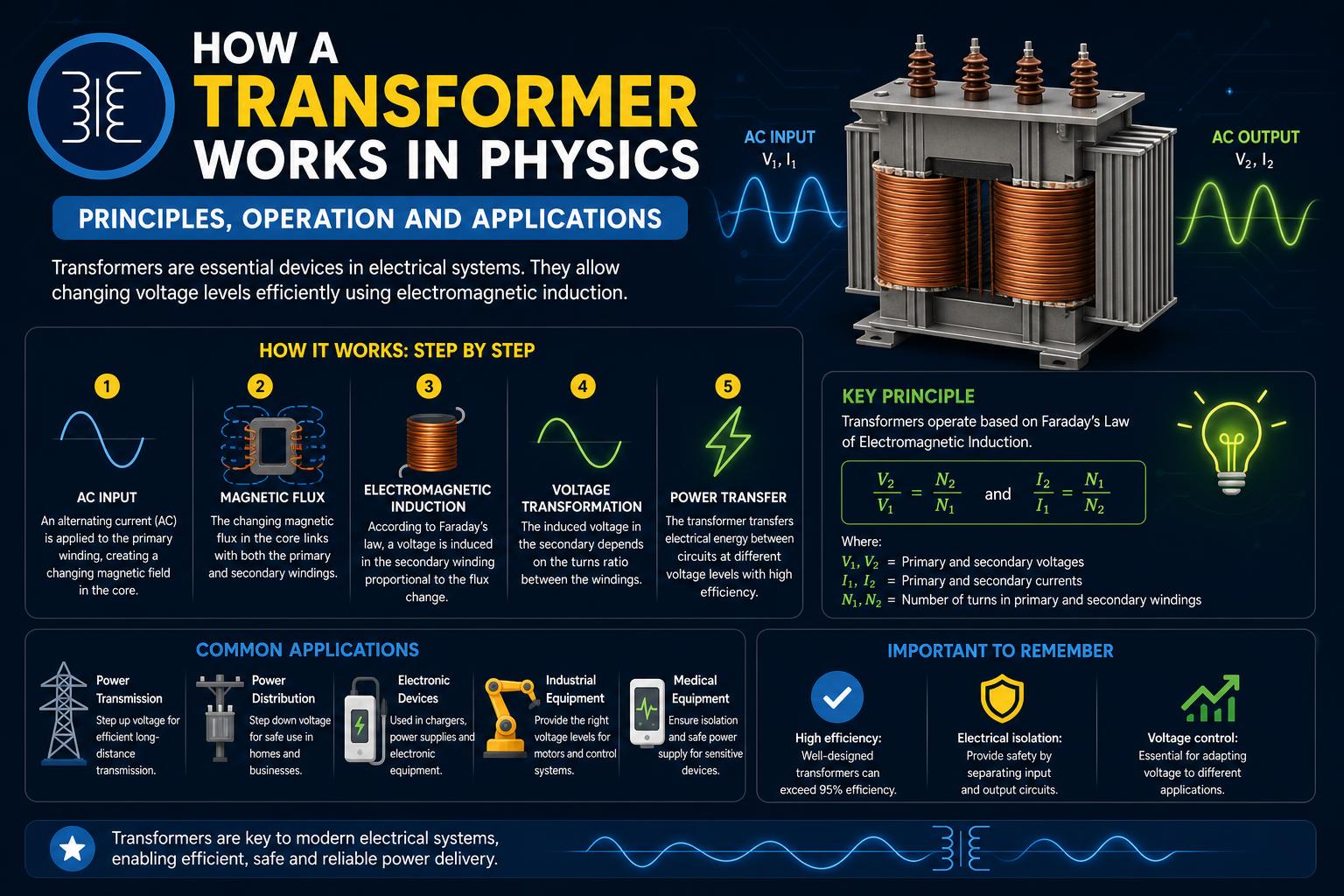
- Transformers rely on electromagnetic induction to change voltage levels in AC circuits.
- The relationship between voltage, current, and coil turns is mathematically defined, ensuring power conservation (minus minimal losses).
- Transformers are essential for efficient, safe power transmission and everyday device compatibility.
Transformers are fundamental devices in the world of physics and electrical engineering, quietly enabling our power grids, consumer electronics, and industrial machines to function efficiently and safely. While most people recognize the name, the way a transformer works remains a mystery to many, sometimes even sparking misconceptions. If you’ve ever wondered how electricity makes its way from far-off power plants to your home outlets—or why your phone charger gets warm—you’re about to find out.
This in-depth article takes you on a journey into the science and practical operation of transformers, blending clear, approachable explanations with expert-level detail. We’ll demystify everything from the simple physics principles behind these devices to the nuanced equations used by engineers, illustrating with real-world examples and addressing common questions along the way. Whether you’re a curious student, a budding engineer, or just someone who loves understanding how things work, this guide is designed for you.
What Is a Transformer and Why Are They So Important?
A transformer is an electrical device that changes the voltage of alternating current (AC) from one level to another using the principle of electromagnetic induction. This might sound straightforward, but this function enables the safe and efficient transport of electricity across cities and through the most sensitive gadgets in your pocket or workplace.
At the heart of nearly every large power system lies the humble transformer. Whether stepping voltage up for high-voltage transmission across hundreds of miles or stepping it down so you can safely plug in your blender, transformers are everywhere: in power stations, substations, your phone charger, your laptop’s power brick, and even inside home appliances.
The Core Principle: Electromagnetic Induction
Transformers operate using electromagnetic induction—the process by which a changing magnetic field creates a voltage in a neighboring conductor. Whenever current flows through a wire, it generates a magnetic field. If you change the strength or direction of this current, you alter the strength or direction of the magnetic field as well.
Alternating current (AC) naturally creates a rapidly changing magnetic field, making it perfect for transformer operation. The beauty of this process is that you can transfer energy from one circuit to another without them physically touching, simply by using the changing magnetic field to ‘induce’ a new voltage.
Transformer Anatomy: Primary, Secondary, and the Magnetic Core
Every transformer has two essential components: the primary coil and the secondary coil. Each coil is just a length of wire wound into loops, called turns, and both coils are wound around a core—generally made of iron or similar magnetic material—that helps direct and strengthen the magnetic field.
- Primary Coil: Connected to the voltage source (such as the power grid), it creates the changing magnetic field.
- Secondary Coil: Receives the induced voltage and supplies it to the intended load (from a city neighborhood to your phone battery).
- Iron Core: Acts as a magnetic ‘bridge’, ensuring the magnetic field produced by the primary winding penetrates the secondary coil as efficiently as possible.
This arrangement means energy transfers between circuits using the language of magnetism, not direct contact. It also means the primary and secondary circuits remain electrically isolated, which provides an extra layer of safety. Most importantly, the number of wire turns on each coil is the secret to controlling whether voltage increases, decreases, or remains about the same.
Why Use Transformers? Power Transmission and Everyday Life
Without transformers, powering anything at a distance would be wildly inefficient, expensive, or outright unsafe. Imagine if every power line had to carry every bit of current needed by your home or workplace, at the low voltage your devices need. The wires would have to be as thick as tree trunks, and you’d lose vast amounts of energy as waste heat—turning the grid into a giant toaster!
Transformers solve this by allowing the grid to transmit power at high voltage (and low current), which minimizes energy losses due to resistance in the transmission lines. Once the electricity arrives near homes or businesses, more transformers step the voltage back down to levels suitable for safe, everyday use. For instance, in the U.S. typical household voltage is around 120 V, while the voltage sent across transmission lines can be hundreds of thousands of volts.
Key Physics Laws: Faraday, Ampere, Ohm, and Conservation of Energy
The operation of a transformer is governed by several foundational laws of physics. Understanding these helps explain not only how transformers work in principle, but also how engineers calculate and optimize them in practice.
1. Faraday’s Law of Induction
Faraday’s Law states that a changing magnetic flux (the total ‘amount’ of magnetic field passing through a coil) induces a voltage (emf) in the coil. In math speak: the voltage induced in the coil is equal to the number of turns multiplied by the rate of change of magnetic flux:
ΔV = N × (dΦB / dt)
In a transformer, both primary and secondary coils are exposed to this changing flux. If the two coils are wound around sections of a common iron core with the same cross-sectional area, then the change in magnetic flux is essentially identical for both.
2. Ampere’s Law
This law tells us that whenever current flows through a wire, it creates a magnetic field—the strength of which depends on the current and the geometry of the coil. In the transformer, increasing the primary current or the number of coil turns boosts the magnetic flux created within the core, thus boosting the induced voltage in the secondary coil.
3. Ohm’s Law
Ohm’s Law describes the relationship between voltage, current, and resistance in a circuit: V = I × R. Understanding this helps clarify what happens to currents and voltages as they enter and exit the transformer, and why changing voltage in one part of a circuit affects current in another, especially when you consider the load’s resistance.
4. Law of Conservation of Energy
Energy isn’t created or destroyed inside a transformer—it’s simply transferred (minus a small amount lost to heating and other inefficiencies, typically less than 1% in quality designs). If 1,000 Watts go in, roughly 1,000 Watts come out (Power = Voltage × Current), but the balance between voltage and current shifts—step up the voltage, and current drops accordingly, and vice versa.
Mathematical Relationships: The Transformer Equations
The operation of any ideal transformer can be captured by the so-called transformer equations, which relate the primary and secondary voltages, the number of turns on each coil, and the respective currents.
- Voltage Ratio: Vs/Vp = Ns/Np
Where Vs is the secondary voltage, Vp the primary voltage, and N denotes the number of coil turns. - Current Ratio: Is/Ip = Np/Ns
Here, Is is the secondary current and Ip the primary current.
This inverse relationship means that as the transformer steps the voltage up, the current steps down, and vice versa—preserving total power. So if you use a transformer to drop 240 V to 120 V, the secondary current will actually double if the power remains constant. That’s why transformers don’t ‘make’ or ‘lose’ power (ignoring real-world losses); they just swap one combo of voltage and current for another.
Step-Up and Step-Down Transformers: What’s the Difference?
Transformers come in two main flavors: step-up and step-down. The distinction is all about what happens to the voltage as electricity moves from one coil to the other:
- Step-Up Transformer: The secondary coil has more turns than the primary, increasing output voltage (and decreasing current).
- Step-Down Transformer: The secondary coil has fewer turns than the primary, decreasing output voltage (and increasing current).
In real-world power grids, a series of step-up and step-down transformers are used at various points to maximize transmission efficiency and ultimately deliver safe voltages to customers. For specific industrial or technical needs, transformers might even provide multiple output voltages depending on which portion of the secondary coil is tapped.
Why Transformers Only Work with AC (Alternating Current)
Transformers need a continually changing magnetic field to induce voltage in the secondary coil—a requirement naturally met by alternating current (AC). With direct current (DC), the magnetic field is steady once turned on, and there’s no further change—hence no induced voltage in the secondary (unless you rapidly connect/disconnect the circuit, which is wildly impractical for most uses).
This AC-dependence is a key reason why the world’s power grids use alternate current, and why transformers are such a vital part of the electric ecosystem.
Real-World Example: Power Transmission and Energy Loss
Let’s explore a classic engineering issue: moving power from a generation plant to the point of use. Suppose you need to deliver 150 kW from a plant over transmission lines with a resistance of 0.5 Ohms. If you transmit at a low voltage (say, 300 V), the required current is huge (Current = Power/Voltage), and the energy lost as heat (Ploss = I2 × R) is enormous—many times the delivered power!
But if you transmit at 300,000 V instead, the current plummets to about 0.5 A and line losses shrink to nearly nothing. This simple trick—boosting voltage to reduce current—is only possible due to transformers, and is why cities, countries, and entire continents can move electricity efficiently over vast distances.
Common Questions and Misconceptions
Does a Step-Down Transformer Double the Power?
No. Power (ideally) stays the same, but what changes are current and voltage. If voltage is halved, current doubles (assuming constant power and negligible losses)—as dictated by the transformer equations. Power conservation rules the day!
Are All Transformers 100% Efficient?
In practice, transformers are incredibly efficient (often above 99%), but not perfect. Small amounts of energy are lost as heat due to resistance in the wires (copper loss) and eddy currents or hysteresis in the core (core loss). These inefficiencies are minimized with high-quality materials and design.
Is There a Limit to the Voltage Transformers Can Handle?
Transformers can be built for extremely high voltages—hundreds of thousands of volts or more—but insulation, material limitations, and safety concerns set practical limits. For the really big stuff, like long-haul international power lines, engineers use carefully designed insulation and cooling systems.
If Transformers Don’t Change Power, Does That Mean My Wall Socket Has the Same Power as a Power Plant?
Although the theoretical maximum power is preserved, practical limits such as circuit protection, wiring capacity, and device ratings mean you can’t draw unlimited power from your wall outlet. Transformers simply allow the available energy to be safely delivered and distributed, scaled to each device’s needs.
Example Calculations and Problem-Solving
Understanding the math behind transformers allows deeper insight into how they are designed and used. Here’s a sample of the real-world-type questions you might come across:
- If you need to convert 240 V to 120 V, a transformer with a primary to secondary coil turn ratio of 2:1 will do the trick.
- For a charger that takes 120 V and outputs 12 V at up to 200 mA, you can calculate the necessary input current and power using the transformer equations and Ohm’s Law.
- If a large power plant once used a transformer to boost voltage to 335 kV and upgraded to 750 kV, you can compare the resulting transmission losses and efficiency using these formulas.
Being able to perform these calculations isn’t just exam prep—it’s exactly what electrical engineers do to ensure safety, efficiency, and reliability in the systems that power our modern world.
A Glimpse at Advanced Transformer Types
Beyond the basic two-coil, iron core setup, there’s a variety of specialized transformers built for different applications. Here’s a quick preview:
- Pad-Mounted and Pole-Mounted Transformers: Used in distribution grids for neighborhoods and businesses.
- Isolation Transformers: Provide electrical isolation for sensitive electronics, enhancing safety.
- Autotransformers: Use a single coil with taps at various points to step voltage up or down.
- Multi-Tapped Secondaries: Allow multiple output voltage choices from a single device, perfect for adjustable supplies and some safety applications.
Each is engineered to meet unique demands for voltage, current, efficiency, and physical constraints, but all rely on the core principles outlined above. For those looking to explore further, companies like Giga Energy and educational resources from platforms such as LibreTexts Physics offer deep dives into applications, troubleshooting, and choosing the right transformer for every need.
Mastering transformers unlocks a deeper understanding of not just modern technology, but also the physics principles that make our electrified world possible. Whether you’re analyzing power loss across a continent, optimizing your latest electronics project, or just plugging in a lamp, it’s transformers that bridge the gap—making high-voltage transmission safe, efficient, and reliable for everyone.