
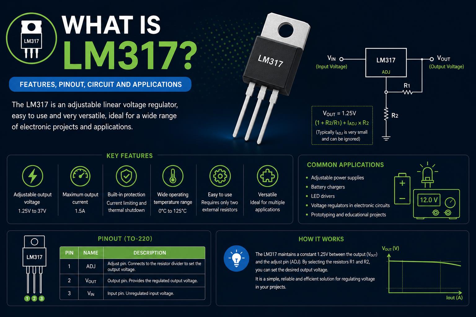
- The LM317 offers fully adjustable voltage output from 1.2V to 37V, supporting up to 1.5A of current for versatile DC regulation.
- It features robust protection including over-current, over-temperature, and short-circuit safeguards for safe, reliable operation.
- Optimal performance hinges on correct resistor selection, adequate heat sinking, and smart use of capacitors and protection diodes.
If you’ve ever tinkered with electronics or tried building a power supply, chances are the name LM317 has crossed your path. From DIY projects on workbenches to sophisticated industrial designs, the LM317 linear voltage regulator has earned legendary status among engineers and hobbyists for over four decades. But what exactly makes the LM317 so iconic in voltage regulation circuits, and why does it still show up in so many designs today?
In this in-depth guide, we’ll take you on a journey through the fascinating world of the LM317. Whether you’re a newcomer looking for basics or a seasoned techie after in-depth operational insights, this article unpacks everything — from how it stabilizes voltages and maintains circuit safety, to the formulas and best practices insiders use to get stable, reliable performance out of their designs. We’ll weave together information from leading sources, real-world applications, pro tips, and even common mistakes beginners make. By the end, you’ll see just why the LM317’s reputation is more than well deserved.
What Is an LM317 and Why Is It So Popular?
The LM317 is a three-terminal adjustable linear voltage regulator introduced by National Semiconductor back in the 1970s. Its popularity is largely due to its versatility: this IC allows users to set any output voltage between roughly 1.2V and 37V, supplying continuous currents up to 1.5A. All this from a compact chip that only needs two external resistors to set the output voltage. Pretty handy, right?
Unlike fixed voltage regulators (like the 7805 or 7812), which lock you into set voltages, the LM317 gives you full control. This flexibility is why it’s found in a dizzying array of applications spanning hobby-level bench power supplies, precision laboratory gear, automotive upgrades, battery chargers, LED drivers, and more complex electronics. And, as the Wikipedia page for LM317 showcases, this regulator is still going strong decades after its debut — a testament to its enduring reliability and ease of use.
Basic Features and Internal Operation
At its core, the LM317 is an adjustable positive voltage regulator IC designed to output a stable, user-selected voltage even if the input or load changes. The three terminals — Input (IN), Output (OUT), and Adjustment (ADJ) — along with two resistors are all it takes to set almost any voltage you need within its range.
- Input Voltage Range: Can accept 3V to 40V DC on the input.
- Output Voltage Range: Adjustable from approximately 1.2V up to 37V.
- Maximum Output Current: Can supply up to 1.5A (with proper heat sinking).
- Thermal Protection: Includes over-temperature and over-current protection circuits to safeguard itself and the load.
- Packages: Available in numerous packages (TO-220, TO-3, SOT23-5, etc.) to fit different layouts and cooling needs.
As emphasized in the DigiKey TechForum guide, the LM317 uses internal negative feedback, relying on a 1.25V bandgap reference, an operational amplifier, and a robust pass transistor to regulate voltage. The feedback loop keeps the voltage between the OUT and ADJ terminals at a stable 1.25V.
Setting the Output Voltage: The Famous LM317 Formula
One of the best things about the LM317 is its elegantly simple method for setting output voltage. All you need are two resistors — typically called R1 (connected between OUT and ADJ) and R2 (from ADJ to ground). The voltage across R1 is kept at 1.25V by the internal reference, and the ratio of R2 to R1 determines the output voltage. The standard formula taken from both Texas Instruments datasheets and technical guides is:
Vout = 1.25V × (1 + R2/R1) + Iadj × R2In practice, Iadj (the small current flowing from the ADJ pin) is very low — usually <100μA — making its effect negligible for most designs. So, a simplified version is often used:
Vout ≈ 1.25V × (1 + R2/R1)Key recommendation: For reliable operation, keep R1 between 100Ω and 240Ω. Staying within this range ensures enough current through the reference and maintains the pass transistor in its linear region, as explained in the DigiKey application guide and IC Components blog. Metal film resistors are best for R1 in high-temperature environments due to superior thermal stability.
Current Regulation Mode
Did you know the LM317 can function as a constant current source too? Instead of using a typical resistor divider, you can configure it so the load itself replaces one resistor. The output current is then set by the reference voltage and chosen resistor:
Iout = 1.25V / RsetThis configuration is widely used for current-limited battery chargers and LED drivers, as noted in the detailed Wikipedia and DigiKey articles.
Protective Features: Why the LM317 Is So Robust
The LM317 isn’t just easy to use — it’s also built tough: Over-current protection kicks in if you try to draw more than rated current, and over-temperature shutdown activates if it gets too hot. This is crucial for keeping both the regulator and your circuit safe if something unexpected happens.
In addition, the IC includes short-circuit and safe operating area (SOA) protection. These means, if you accidentally short the output, the LM317 throttles itself to avoid catastrophic damage. Its safeguards ensure that the LM317 can survive a fair bit of abuse compared to more primitive regulators.
Choosing Capacitors and Diodes: Practical Circuit Considerations
For stable, quiet operation, don’t forget your capacitors! Here’s what pros recommend:
- Input Capacitor: If the main smoothing capacitor is more than 15 cm (6 inches) from the regulator, add a 0.1μF ceramic or 1μF tantalum capacitor at the IN pin to suppress high-frequency noise.
- Output Capacitor: Place a capacitor (around 1μF) on the OUT pin to improve transient response and reduce output noise.
- Adjustment Pin Capacitor: Adding a small-value capacitor (e.g., 10nF) from ADJ to ground improves ripple rejection significantly.
- Protection Diodes: In scenarios where output capacitance is high or the output is exposed to reverse voltages (like batteries or big capacitors), use a diode between OUT and IN, and between ADJ and OUT to prevent current from flowing the wrong way and damaging the IC.
All of these tricks, highlighted in a variety of the sources above, help prevent oscillation and ensure reliable operation for years to come.
Common Errors and How to Avoid Them
Even though the LM317 is beginner-friendly, here are some common gotchas you’ll want to dodge (with tips sourced from DigiKey and Reddit contributors):
- R1 Value Too High: Going over 240Ω for R1 can result in unstable regulation because it reduces the minimum load current needed for correct operation. Stick to the 100–240Ω range.
- Overheating: In the LM317, the difference between input and output voltage gets dissipated as heat. For example, if you use a 15V input and want 5V out at 1A, you’ll need to handle 10W of heat! Always use proper heat sinking and remember: the power dissipated equals (Vin – Vout) × Iout.
- Adjustment Pin Current Ignored: Most of the time, you can neglect Iadj, but in ultra-precision cases or high-output-resistance setups, consider it to ensure accurate voltage.
- Feedback Path Failure: If you use a potentiometer in the R2 slot and its wiper fails, the output may shoot up close to the input voltage — likely destroying sensitive connected electronics. To protect your project, wire the pot carefully, add a parallel resistor to limit excursion, or use a zener/crowbar circuit for overvoltage protection.
- Input-Output Voltage Differential: The LM317 requires the input to be at least 3V higher than the output under load, or regulation is lost.
Calculating Output Voltage and Choosing Resistors
Let’s work through a practical example, synthesizing advice from both DigiKey and the Reddit circuit designers:
Suppose you want a stable 6.4V DC output using standard values. Keeping R1 at 100Ω (for safe current), you’d calculate R2 as follows:
Vout = 1.25 × (1 + R2 / R1)
6.4 = 1.25 × (1 + R2 / 100)
R2 = 412Ω
Both 100Ω and 412Ω resistors are available in precision (1%) tolerance series, minimizing output drift. If you want a variable output (e.g., 1.25V to 8V), set R2 as a potentiometer in parallel with a fixed resistor to cap the maximum voltage even if the wiper fails.
Pro tip: Output voltage accuracy is directly related to the tolerance of R1 and R2. For best results, use 1% tolerance (or better) resistors, and if you really need precision, consider 0.1% versions.
Understanding Minimum Load Current and Regulation Issues
For the LM317 to regulate properly, a minimum output current must flow — typically about 3.5mA (sometimes specified up to 10mA depending on manufacturer). If the output load drops too low, the regulator might lose control of the output voltage and drift higher than expected. Many engineers add a ‘bleeder’ resistor on the output to guarantee this minimum load current is always present, ensuring accurate regulation even for low-current circuits.
Soft-Start and Power-Up Behavior
If surge currents on power-up are a problem — especially with sensitive loads — you can implement a soft-start circuit using a transistor, capacitor, and additional resistor. As described in the IC Components article, the capacitor charges gradually when the supply turns on, causing the output voltage to ramp up slowly rather than jump instantly. This protects both the regulator and fragile circuitry downstream from nasty voltage spikes. Diodes can provide a quick discharge path for subsequent power cycles, readying the system each time it turns on.
Thermal Considerations for Reliable Operation
The biggest challenge when using the LM317 at higher currents or significant Vin–Vout differences is managing heat. Since it’s a linear (not switching) regulator, all the voltage it drops appears as wasted heat. This means the TO-220 or TO-3 case can get hot for high loads — sometimes very hot. To avoid problems:
- Pick an appropriately rated heatsink for your package and application.
- Recognize that above a certain ambient temperature, the IC may reduce output automatically to prevent self-destruction.
- If you’re really pushing the limits (high current, high input voltage), add forced airflow or even a fan.
Remember, if you exceed the thermal resistance or junction temperature limits (typically 125°C for the LM317’s silicon), the regulator will enter thermal shutdown to protect itself — but it’s always safer not to rely solely on these internal features.
Comparison With Other Voltage Regulators
The LM317 is an adaptable, adjustable regulator, which sets it apart from the 78xx and 79xx families that provide only fixed voltages (like 7805 for 5V, 7812 for 12V). While the 78xx series can be tweaked using resistor dividers, their quiescent current is higher and less stable. The LM317’s low and consistent adjustment pin current makes its output more accurate and less sensitive to resistor tolerances — making it the preferred choice for precision applications.
The negative-voltage cousin LM337, as used in symmetrical power supplies, follows the same concepts for negative rails.
Other alternatives, such as the LT1086 and higher-current LM350, exist but sometimes lack the LM317’s flexibility in adjustment or ready availability.
Typical Uses and Applications for the LM317
- Bench Power Supplies: Adjust output voltage for any device under test.
- Battery Chargers: Easily set the charging voltage for different battery chemistries.
- LED Drivers: Use as a current regulator for high-power LEDs.
- Adjustable On-Card Regulators: One chip can supply different voltages to various sections.
- Precision Reference Supplies: Stable outputs for analog and digital circuits (sensors, ADCs, op-amps).
- Tracking Pre-Regulators: Provides an initial stable voltage for more complex supplies downstream.
Want to dive deeper? See the wide array of application circuits in the Texas Instruments datasheet.
Tips From Experienced Engineers
Veteran designers and Reddit hobbyists alike stress a few practical tips:
- Don’t ignore datasheet recommendations. Even if you use standard resistor values, confirm your output voltage with a multimeter, as small differences in component tolerance can matter in critical designs.
- Plan for thermal management early. Calculate worst-case heat dissipation (input voltage spikes, heavy loads) and design your enclosure or PCB with enough airflow or metal mass to dissipate heat.
- Always test for worst-case scenarios. Some users note that over time, potentiomers can become noisy or fail — factor in protective measures from the get-go.
A Brief History: The LM317’s Legacy
Created by Bob Dobkin at National Semiconductor in the early 1970s, the LM317 quickly became a staple in electronics. Dobkin himself, in oral histories available online, counts it among his favorite achievements. It’s amazing how a chip developed over 50 years ago still delivers value in modern applications and is praised for the flexibility and simplicity it offers to every generation of electronic enthusiasts. The device’s design, built around the bandgap reference and simple negative-feedback amplifier, became the blueprint for future adjustable regulators — and its architecture remains fundamentally unchanged even now.
The LM317 has cemented its legendary status thanks to its simplicity, flexibility, and robust engineering. It allows users to create custom power rails with minimal hassle, provides protection against common electrical faults, and adapts to a wide range of applications—from classroom kits to high-precision instruments. Whether you are building your first benchtop power supply or a precise laboratory reference, the LM317 remains an icon of voltage regulation, proving that some classics endure for a reason.