
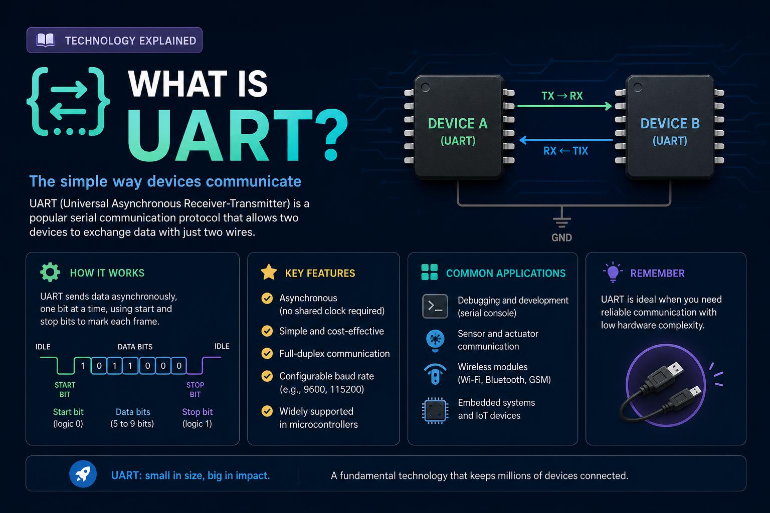
- UART (Universal Asynchronous Receiver/Transmitter) enables simple, reliable serial communication with just two wires by converting data between parallel and serial formats.
- There are several variants—TTL, RS-232, RS-485—each suited to different voltages, distances, and types of networks, with additional protocols layered on top for robustness or multi-device scenarios.
- Correct operation requires matching configuration (baud rate, data bits, voltage), and buffers or flow control to prevent data loss, with practical applications ranging from hobbyist modules to industrial multiplexed sensor networks.
Have you ever wondered how your computer talks to a GPS module, a Bluetooth chip, or even some of those legacy devices like old-school printers and modems? The unsung hero making all those connections possible is the UART, or Universal Asynchronous Receiver/Transmitter. While today’s tech world is all about blazing-fast USB and wireless links, UARTs are still out there quietly handling serial data transmission in everything from hobbyist microcontroller boards to complex industrial systems.
If you’re curious about what UARTs are, how they work, their history, protocols, variants, and why they still matter in modern electronics—this guide is about to bring clarity. Let’s demystify UARTs, debunk some common mistakes, and explore why they remain irreplaceable in so many embedded applications and communication interfaces.
Understanding the Basics: What is a UART?
UART stands for Universal Asynchronous Receiver/Transmitter. Despite the somewhat intimidating name, a UART is actually a simple hardware component (either a dedicated chip or built into a microcontroller) that converts data between parallel and serial formats. Its main job? Sending and receiving serial data between digital systems, such as between a microcontroller and a connected sensor or peripheral.
Unlike dedicated communication protocols like SPI or I2C, UART is not a communication protocol per se but a logic circuit. It doesn’t prescribe a specific messaging protocol or address scheme—rather, it defines how bits are sent: asynchronously, serially, and in a format that both sender and receiver agree upon.
The big win of UART: it typically requires only two wires to establish simple, reliable, point-to-point communication—“Tx” (transmit) and “Rx” (receive). That simplicity, plus its wide support, makes UART one of the most accessible and popular ways to enable serial data exchange in electronics.
How UART Communication Works
UARTs communicate asynchronously, meaning there’s no dedicated clock line tying them together. Instead, data is transmitted in packets, and both sides must agree on the speed of communication, known as the baud rate. Along with the main data, each packet is marked by a start bit signaling the beginning, and one or more stop bits to indicate the end.
Here’s a step-by-step overview of how UART transmission unfolds:
- Data Preparation: The transmitting UART takes parallel data from a source such as a CPU, assembles it into a packet. This packet includes a start bit, a configurable number of data bits (typically 5 to 9), an optional parity bit for error checking, and one or two stop bits.
- Serial Transmission: The UART sends bits one after the other over the Tx line at the pre-agreed baud rate.
- Reception: The receiving UART monitors its Rx line. When it detects the falling edge (high to low transition) of the start bit, it synchronizes and samples the following bits in step with the baud rate.
- Data Decoding: After all bits, including optional parity and stop bits, are received, the UART converts the serial stream back to parallel data and transfers it to the receiving device.
This setup enables point-to-point data exchange between devices with minimal wiring and no need for a separate synchronizing clock.
Breaking Down the UART Data Packet: Frame Structure
Every chunk of data transmitted by UART is packaged in a ‘frame’ or packet, which comprises several distinct fields:
- Idle State: When not transmitting, the line remains at a high voltage level (logic ‘1’, also known as ‘mark’). This is useful for line integrity checks and detecting if a device is unplugged or malfunctioning.
- Start Bit: Transmission kicks off with a start bit—a logic ‘0’ (‘space’), signaled by pulling the Tx line low. The receiver uses this transition to synchronize and begin bit timing.
- Data Bits: These carry the payload—usually 5 to 9 bits, most commonly 7 or 8. Data is nearly always sent with the Least Significant Bit (LSB) first. For example, the ASCII character ‘S’ (binary 1010011) is transmitted as 1 1 0 0 1 0 1.
- Parity Bit (Optional): An extra bit for error detection, configured as even or odd. The sending UART counts the number of ‘1’s in the data; the parity bit is set to ensure the result matches the parity rule. The receiving UART repeats the check; if the result doesn’t match, it knows some bits changed during transmission.
- Stop Bit(s): After the data and optional parity, one or two stop bits return the line to the idle (high) state. This gives the receiver time to process the byte and prepare for the next frame.
For typical UART configuration (8 data bits, no parity, 1 stop bit—”8N1″), each frame contains 10 bits per character transmitted, giving about 80% protocol efficiency. This may sound modest compared to Ethernet’s higher efficiency with large packets, but UART excels with small, simple exchanges—precisely where Ethernet can be wasteful.
The Hardware Behind UART: Components and Functions
A UART module is more than just a pair of pins: it contains several crucial subcircuits that handle the conversion, synchronization, and buffering needed for reliable serial data transfer.
Main internal elements found in a UART design include:
- Clock Generator: Provides the timing for bit sampling and transmission, usually running at a frequency that’s a multiple of the baud rate (such as 8x or 16x) to guarantee accurate bit detection.
- Shift Registers: These convert between parallel data (like a byte on the data bus) and serial transmission (one bit at a time across the Tx or Rx line).
- FIFO Buffers: These are short-term memory circuits that queue incoming and outgoing bytes, allowing CPUs to read or write data in bursts and reducing the risk of overflow or lost bytes—vital at high communication speeds.
- Transmit/Receive Control: Logic that kicks off or stops sending data, manages interrupts, and handles flow-control signals.
- Read/Write Control: Coordinates data exchange with the attached processor or memory, flags when new bytes are ready or transmission is complete, and can trigger system interrupts if required.
On modern microcontrollers, UART hardware is often built directly into the chip, letting software interact with transmit/reception registers and configure parameters like parity, baud rate, and stop bits.
How UART Differentiates from Other Protocols (SPI, I2C)
UART is sometimes confused with other serial buses like SPI and I2C, but its architecture is fundamentally different:
- UART is asynchronous: It doesn’t require a shared clock line. Synchronization is managed via start and stop bits.
- SPI is synchronous and uses a dedicated clock, plus additional wires for select signals, supporting much higher speeds and multi-master/multi-slave networks.
- I2C is synchronous, supports multiple masters and slaves, and transmits data or clock jointly on the same pair of wires with device addressing.
UART excels at simple, direct device-to-device links where only two endpoints are required, with a minimal wire count and configuration. If you need to connect more than two devices or handle multiple masters, protocols like SPI and I2C become more suitable.
UART Modes of Operation: Simplex, Half-Duplex, Full-Duplex
UART communication can be set up in three basic modes, each serving different application needs:
- Simplex: Data travels in only one direction—from transmitter to receiver. The receiver never sends data back (think GPS or RFID tags that only send position or an ID).
- Half-Duplex: Communication can go both ways, but not at the same time. Devices take turns transmitting and receiving, often used in bus or multi-drop networks where collisions must be avoided.
- Full-Duplex: Data is simultaneously sent and received, with separate wiring for Tx and Rx, enabling real-time, two-way communication as seen in PC to modem links.
Many UARTs are designed for full-duplex operation, but the exact mode depends on the chipset, wiring, and application requirements.
Understanding UART Variants and Physical Interfaces
The UART circuit itself doesn’t care about electrical characteristics—it only handles logic levels to represent ‘1’s and ‘0’s. However, the voltage and wiring needed to transfer those UART signals across real-world connections varies by application. Here are the most common implementations:
TTL Serial (Logic-Level UART)
TTL (Transistor-Transistor Logic) serial refers to UART signaling at logic voltages directly compatible with the microcontroller or digital system. Typically, the voltage range is either 0–5V or 0–3.3V, depending on the platform. A ‘high’ (logic 1, or ‘mark’) is the higher voltage (e.g., 3.3V or 5V), while a ‘low’ (logic 0, or ‘space’) is 0V.
TTL UART is commonly used for on-board communications between chips, or very short cable runs. It is simple, requires only a ground reference shared by both devices, and needs no level converters as long as both devices use compatible voltage domains. However, the lack of standardization across voltage levels means a 5V UART can easily fry a 3.3V device without a level-shifter.
Examples of TTL UART usage:
- Arduino or Raspberry Pi serial headers (for programming or debugging)
- On-board connections between a controller and modules (GPS, Bluetooth, RFID, etc.)
- Arduino and Raspberry Pi official documentation provides pinouts for TTL UART use
- USB-to-TTL UART adapters based on FT232R or CP2102 chips
Limitations: Because TTL UART is single-ended (referenced to ground) and uses narrow voltage swings, it is prone to noise over longer distances. In most cases, you’re limited to a meter or two of reliable cable—beyond that, consider RS-232 or RS-485.
RS-232: The Classic Serial Standard
RS-232 is the granddaddy of serial standards, originally specified in the 1960s for connecting computers and peripherals. It’s the protocol behind all those chunky DB9 and DB25 connectors on vintage gear. At its core, RS-232 uses UART data framing, but with a few notable twists:
- Voltage Levels: RS-232 levels are much higher and inverted compared to TTL. Logic ‘1’ is represented by -3V to -12V; logic ‘0’ by +3V to +12V.
- Single-Ended: One wire per signal, referenced to a shared ground.
- Robustness & Cable Length: Its high voltage swings allow for reliable transmission up to 15 meters (about 50 feet). Standard baud rates typically reach 115,200 bps, though short runs can handle up to a few Mbps.
- Connectors: Classic DB9 and DB25 connectors carry several signals beyond Tx, Rx, and GND—such as RTS, CTS, DTR, DSR, etc.—to support hardware flow-control and modem applications. However, for basic communication, only three pins are necessary.
- Directionality: RS-232 enables point-to-point, full-duplex transfer (simultaneous send and receive), but it only supports a single transmitter and a single receiver per link.
Adapters like the MAX232 are commonly used to translate between microcontroller logic and RS-232’s higher, inverted voltages. Never connect an RS-232 Tx pin directly to a TTL UART or microcontroller pin unless you’re sure a level shifter is in place—this mistake can quickly destroy the lower-voltage chip!
Despite being old-fashioned in the PC space, RS-232 remains prevalent in industrial, laboratory, and networking equipment. USB-to-RS-232 adapters are also freely available if you need to connect old serial peripherals to modern computers.
RS-485: The Industrial Workhorse
RS-485 (also called EIA-485) takes UART-based communication to new heights, making it a favorite for industrial and building automation networks. Here’s what sets it apart:
- Differential Bus: Uses two wires (A and B) carrying equal and opposite voltages. A logic ‘1’ is a positive voltage difference (A > B), while a ‘0’ is negative (A < B). This balanced signaling provides exceptional immunity to electrical noise, making it ideal for long cables even in noisy factories.
- Multi-Drop Capability: RS-485 isn’t limited to point-to-point; one pair of wires can serve up to 32 (or more with modern transceivers) devices on the same bus. Both transmitters and receivers can be connected together, allowing for multi-master or master/slave topologies.
- Half-Duplex (Typical): The most common mode uses a single pair of wires for both Tx and Rx—devices coordinate turn-taking in software. Full-duplex is possible (using two pairs of wires), but less common in practice.
- Distance & Speed: RS-485 supports cable lengths up to 1200 meters (~4000 feet) at lower speeds (e.g., 100 kbps), and data rates up to 10 Mbps (or more) over short cables.
- Examples: Widely used for protocols like Modbus RTU, Profibus, BACnet MSTP, and DMX512 (stage lighting).
Since all devices share the bus, RS-485 requires that only one device drives the line at a time. RS-485 chips typically have a ‘driver enable’ pin to control when the device drives the line and when it sits idle (in high-impedance “listening” mode).
Physical Layer Comparison: RS-232 vs. RS-485 vs. TTL UART
| Feature | RS-232 Serial | RS-485 Serial | TTL Serial |
|---|---|---|---|
| Signaling | Single-ended, inverted logic (-3 to -12V for ‘1’, +3 to +12V for ‘0’) |
Differential, non-inverted logic (A>B = ‘1’, A |
Single-ended, non-inverted logic (0V to Vcc, usually 3.3V or 5V; ‘high’ = 1) |
| Maximum Devices | 1 transmitter, 1 receiver Point-to-point only |
Multi-drop bus, up to 32 receivers (or more) Supports many devices on one bus |
1 transmitter, 1 receiver Point-to-point |
| Range | Up to ~15 meters (50 ft) at standard speeds | Up to ~1200 meters (4000 ft), lower speeds for max distance | Up to a few meters; best under 1-2 meters for reliability |
| Data Rate | Up to 115 kbps standard, higher possible on short links (1 Mbps+) | Up to 10 Mbps (short lines); 100 kbps at 1200m | High as chip allows; typically up to several Mbps on-board |
| Common Use Cases | Old PC COM ports, lab instruments, industrial config ports | Industrial networks, building automation, sensor buses, DMX lighting | On-board chip-to-chip comms, microcontrollers, modules (GPS, Bluetooth, sensors) |
Key Parameters for UART Setup
For UART communication to work, both endpoints must agree on the following settings:
- Baud Rate: The speed at which bits are sent (bits per second). Common values: 9600, 19200, 57600, 115200 bps.
- Voltage Level: Must match between devices. For example, both 3.3V or both 5V; otherwise, a level shifter is necessary.
- Data Bits: Size of data field (could be 5, 6, 7, 8, or 9 bits; usually 8).
- Parity: None, even, or odd. Parity adds basic error detection.
- Stop Bits: One or two; most systems use one.
- Flow Control: Optional; could be hardware (RTS/CTS) or software (XON/XOFF).
If there’s any mismatch between these parameters, communication will fail, leading to data corruption, framing errors, or other problems. Also, remember that at higher baud rates or longer cables, even small discrepancies in baud rate or voltage levels can cause loss of synchronization and data errors.
Common UART Applications: Where and Why UART Is Used
UARTs have survived decades of technological change because their simplicity, reliability, and widespread support make them perfect for a wide range of tasks—even in modern systems:
- Programming and debugging embedded systems (using TTL UART headers)
- Connecting GPS, Bluetooth, RFID, and other modules in DIY or professional projects
- Console ports for network and industrial equipment (often via RS-232 or RS-485)
- Data logging with sensors distributed across large areas (RS-485 is a favorite for multi-drop sensor networks)
- Stage lighting (DMX512 protocol over RS-485), building automation (BACnet MSTP), or factory control (Modbus RTU transport)
- Any scenario where simple, two-wire communication suffices or where differential signaling is needed for robust links
Legacy to Modern: A Brief History and Evolution of UARTs
The concept of serial data transmission dates back to forebears like the telegraph and early teletypewriters. The first serial protocols were mechanical, using time pulses to signal characters (as in Morse code), but by the 1960s–70s, electronic UARTs emerged to automate and accelerate data exchange without moving parts.
DEC (Digital Equipment Corporation) designed the first stand-alone UARTs for their PDP computers. This innovation soon condensed into integrated-circuit form—Western Digital’s WD1402A (circa 1971) among the earliest popular single-chip UARTs. Wikipedia lists significant landmarks in UART evolution, including:
- National Semiconductor 8250: Used in original IBM PCs; simple, with 1-byte buffers.
- 16550/16550A: Added 16-byte FIFO buffers, allowing reliable high-speed serial comms without constant CPU attention. Spawned many descendants with larger buffers and advanced features.
- Multi-port UARTs (DUART, QUART, OCTART): Combining 2, 4, or 8 UARTs in a single chip, supporting multi-channel serial applications.
- USB to UART Bridges: These modern chips (e.g., FTDI FT232R, Cypress, ASIX AS99100, and Exar XR series) translate between high-speed USB and one or more UARTs, providing the ubiquitous “Virtual COM Port” feature in every PC today.
Many embedded CPUs still feature on-chip UARTs for integrating with peripherals and for system debugging. Even as physical RS-232 ports disappear from laptops, the UART standard itself thrives beneath more modern connectivities.
Major UART Models and Features
Here’s a snapshot of popular UART models and what set them apart:
- WD1402A (circa 1971): First single-chip UART for general sale.
- 8250/16450: Original PC and AT UARTs; 1-byte buffers, limited to modest speeds without data loss.
- 16550A: 16-byte FIFO for transmit/receive, increased allowed data rates dramatically, reducing CPU load.
- 16650–16950/16C950: 32, 64, and even 128-byte buffers, DMA support, advanced flow-control. Higher data rates (1.5 Mbps, 3 Mbps, and above).
- DUART/QUART/OCTART: Dual, quad, or octal port variants for multi-channel communications. Models include NXP’s 28L194 (quad) and Exar XR16L788 (octal).
- PCl Express UARTs (ASIX AS99100 series, Exar XR17Vxxx): Multi-port UARTs with high buffer counts, DMA, and support for 6–25 Mbps speeds per port.
Key feature upgrades over time: larger buffers for FIFO operation, programmable interrupt triggers, DMA support, increased maximum data rates, automatic flow-control, multi-drop networking, and the ability to adjust for non-standard bus timings.
Common Challenges and Error Handling in UART Communication
UART is reliable under most circumstances, but several issues can disrupt smooth communication:
- Baud Rate Mismatch: If transmitter and receiver speeds drift apart by more than ~10%, bit sampling goes out of sync and data lost or misinterpreted.
- Voltage Level Incompatibility: Mismatched levels between devices (e.g., 5V to 3.3V) can cause unreliable communication or destroy sensitive components.
- Frame Errors: Occur when the expected stop bit is missing, often due to noise, line glitches, or configuration mistakes. Receivers typically set a framing error flag for the host CPU.
- Overflow/Overrun: If incoming bytes are not read from the UART buffer quickly enough, additional data can be lost. FIFO buffers mitigate this issue, but at very high speeds or with a busy host CPU, overruns still pose risks.
- Noise/EMI: Single-ended signals (TTL or RS-232) are susceptible to noise, sometimes flipping bits in transit, especially over unshielded or long wires.
Savvy design and proper configuration—such as using flow control, matching settings carefully, and choosing appropriate interface chips—solve most everyday problems.
Emulating UART in Software (“Bit Banging”)
Not every microcontroller has enough built-in UARTs—or any at all—but you can still “fake” UART protocol entirely in software! The technique, called bit-banging, uses general-purpose I/O pins and carefully timed routines to mimic UART’s timing and bit structure.
Pros: Avoids needing a hardware UART; flexibility for custom signaling or unique project constraints.
Cons: Consumes considerable CPU time; not practical for very high data rates or complex multitasking systems.
Popular microcontroller platforms like Arduino (official Arduino page) and Teensy offer software serial libraries. Raspberry Pi Pico with its Programmable I/O (PIO) lets you write custom state machines for UART emulation at the hardware level. NXP FlexIO is another hardware-assisted bit-banging solution.
Advanced UART Features: Flow Control and Buffering
As computers and peripherals became faster, keeping up with high data rates led to new challenges. Early UARTs had only 1-byte buffers, requiring constant CPU checking. Loss of data—”overruns”—was a constant risk at fast transmission rates, especially in multitasking systems or when other I/O like disk controllers blocked CPU interrupts for more than a millisecond.
The evolution to FIFO (First-In, First-Out) buffers marked a major leap:
- 16-byte, 32-byte, 64-byte, 128-byte, and even larger buffers allow the CPU more time to handle interrupts and fetch pending data.
- With a 16-byte buffer, systems could jump from ~9600 bps limits to well over 150 kbps.
- Larger buffers and DMA support allow reliable serial ports reaching several megabits per second (and for custom applications, even faster!).
Flow control mechanisms are vital for preventing buffer overflow:
- Hardware: Signals like RTS (Request to Send) and CTS (Clear to Send) pause and resume transmission between modem or device and host.
- Software: Special characters (XON/XOFF) sent in-band to pause or restart data flow.
Even with modern high-speed and USB-based solutions, classical UARTs with hardware flow control remain workhorses for reliable, robust communication where timing isn’t always predictable.
Practical Tips: Getting UARTs Working in Your Projects
Here’s what you need to keep in mind for UART success:
- Match baud rate and data format: Both devices need to agree, or the receiver will misinterpret frames.
- Check voltage compatibility and use level shifters/transceivers if needed: Connecting RS-232 directly to TTL UART pins without translation can instantly damage chips.
- Isolation and EMI filtering: For long runs or noisy environments, differential transceivers (RS-485) and opto-isolators enhance robustness.
- Cable quality and length: Use shielded, twisted-pair cabling for anything beyond a short on-board link.
- Use FIFO buffers or software tuning to avoid overruns: If your project supports high speeds, be sure your buffer is large enough and the host CPU isn’t monopolized by other tasks.
- Debug with logic analyzers or oscilloscopes: Subtle mismatches in setup, or timing errors, can be easily spotted and analyzed if you can visualize the waveform.
Typical UART Use Cases in Embedded Development
UARTs are the go-to interface for numerous tasks in hobbyist and industrial electronics alike. A few real-world scenarios include:
- Programming and debugging microcontrollers: Many boards expose a UART to flash firmware or inspect debug logs.
- Sensor networks with RS-485: Long-distance, multi-drop sensor arrays for data logging and automation use UART framing via differential lines for noise immunity.
- Connecting to cloud via cellular or GPS modules: Most cellular, GPS, and Bluetooth modules communicate over UART, typically via TTL headers or USB-UART bridges.
- PC-to-device communication and retro computing: Modems, point-of-sale systems, laboratory instruments, and legacy installations still rely on RS-232 links for service and data transfer.
- Industrial controls and building management: Many HVAC, process control, lighting, and access control systems use RS-485 UART networks to coordinate devices over hundreds or thousands of meters.
UART Configuration and Troubleshooting Examples
Let’s walk through how you’d typically configure and debug a UART link:
- Select the baud rate: 9600 bps is a common default, but if both devices support it and if your cables are short, higher speeds like 115200 bps may be chosen.
- Set data bits/parity/stop bits: For most modern uses, ‘8N1’ (8 data bits, no parity, 1 stop bit) is standard.
- Connect the wires: Rx pin of Device A to Tx of Device B; Tx of Device A to Rx of Device B; GND lines shared. Add an RS-232 transceiver (e.g., MAX232) if either end is at RS-232 logic levels, or RS-485 differential transceiver if using that bus.
- Double-check levels: Never connect RS-232 directly to TTL; use adapters.
- Power up and test: Use a serial terminal or logic analyzer to check for clean, correctly formatted character exchange. If you see garbled output, check baud rate and parity settings on both sides.
- Troubleshoot errors: Frame or parity errors usually mean a formatting mismatch; data loss means the receiver isn’t keeping up with the transmission—try reducing the baud rate or increasing buffer size.
Key Takeaways for Choosing a UART Solution
- For short, simple links between two chips or boards, TTL UART is fast, easy, and low-cost—just watch out for voltage mismatches.
- For robust, point-to-point communication with legacy devices or long cables, RS-232 is the standard—make sure you have the right voltage translators.
- If you need ruggedness, long cable runs, or multi-drop networking, RS-485 rules—just don’t forget driver enable logic and distinctive bus addressing.
Modern UARTs offer a rich feature set—FIFO buffering, DMA, flow control, high data rates, and multiple channels—so choose the right chip or microcontroller to suit your project’s needs.
Universal Asynchronous Receiver/Transmitter technology may be one of the oldest forms of digital communication still in common use, but its blend of simplicity, flexibility, and reliability ensures it remains relevant despite the onslaught of more advanced interfaces. Whether you’re a hobbyist connecting a GPS to your Raspberry Pi, an engineer building multi-sensor networks for industrial control, or someone maintaining legacy systems—knowing UART inside and out is an essential skill in the toolbox of every electronics enthusiast and professional.
Your Guide to Arduino IDE: Download, Features, and Comprehensive Tips