
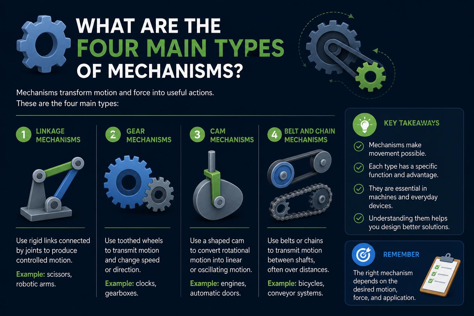
- Mechanisms are primarily categorized into four types: planar, spatial, cam/follower, and gear mechanisms, each defined by their motion and joint types.
- Understanding kinematic pairs (lower and higher pairs) and degrees of freedom is crucial for accurate mechanism design and motion analysis.
- Applications range from everyday machines like engines and cranes to sophisticated robotics, highlighting the versatile importance of these mechanisms in engineering.
Whether you’re tinkering with machines, studying engineering, or simply curious about what keeps the mechanical world in motion, understanding mechanisms is a must. Every mechanical system, from the intricate parts of a watch to the robust workings of heavy machinery, depends on carefully designed mechanisms to transmit force and produce the desired movement. But not all mechanisms are created equal—some are elegantly simple, while others are marvels of multidimensional design.
If you’ve ever wondered what the main types of mechanisms are and why engineers put so much thought into their classification, you’re in the right place. This article offers a friendly, in-depth look at the four primary types of mechanisms, how they’re built, where they’re used, and why understanding their differences is essential if you want to make sense of machines and their seemingly endless variety.
What is a Mechanism?
In engineering, a mechanism is an assembly of rigid bodies—called links—connected by joints in such a way that they produce a desired relative motion between parts. Think of a mechanism as the backbone of a machine, dictating how components interact and how motion is guided along specific paths. Their design not only ensures proper function but also dramatically impacts efficiency, reliability, and longevity.
Understanding Kinematic Pairs (Joints)
The connection between two elements in a mechanism is known as a kinematic pair, or simply a joint. Joints can be classified mainly into two groups:
- Lower pairs: These joints maintain surface contact between elements. Examples include revolute (hinged), prismatic (slider), screw (helical), cylindrical, spherical (ball), and planar joints.
- Higher pairs: These involve line or point contact, such as gear teeth meshing or cam and follower interactions.
The type of joint is important because it defines the degrees of freedom (DOF) between parts—essential for predicting, controlling, and optimizing a system’s movement.
The Four Main Types of Mechanisms
All the mechanisms used in engineering can be organized into four principal categories:
- Planar Mechanisms
- Spatial Mechanisms
- Cam and Follower Mechanisms
- Gear Mechanisms
1. Planar Mechanisms
Planar mechanisms are the most common mechanical systems, where all motion is confined to a single plane or to parallel planes. This means that every point on the mechanism moves parallel to a fixed plane. Their simplicity facilitates design and analysis, making them fundamental in applications ranging from linkages to levers in everyday machinery.
Key features of planar mechanisms:
- Components move only in two translation directions and one rotation.
- All calculations and synthesis can be managed using planar geometry.
- Common applications include four-bar linkages, levers, hinges, scissors, among others.
Four-Bar Linkage
The four-bar linkage is perhaps the best-known planar mechanism. It comprises four links connected via pin joints forming a closed loop. Usually, one link is fixed (the ‘ground’), while the other three are mobile.
- Crank (input link): Receives input, often from a motor.
- Coupler (intermediate link): Transfers motion between input and output links.
- Follower (output link): Delivers the generated motion or force.
- Applications: Used extensively in engine valves, vehicle suspensions (e.g., Watt’s linkage), crane arms, and folding devices.
Types of Motion in Planar Mechanisms
- Function Generation: Defines specific relationships between input and output motion.
- Path Generation: Ensures a component traces a particular trajectory.
- Motion Generation: Controls the orientation of a link during operation.
Planar mechanisms are favored for their simplicity, ease of analysis, and high reliability. Their straightforward manufacturing and maintenance are additionally advantageous due to the lack of out-of-plane movements.
Other Examples of Planar Mechanisms
- Slider-Crank Mechanism: Utilized in pistons, compressors, and engines—variations of four-bar linkages with a sliding element replacing one link.
- Parallelogram Four-Bar Linkage: Ensures parallel motion, suitable for loader arms and lifting platforms.
- Block Feeders, Ratchet Mechanisms, Geneva Wheels: Specialized planar linkages for controlled motion, intermittent drives, and timing devices common in watches and automation equipment.
2. Spatial Mechanisms
Spatial mechanisms enable movement in three-dimensional space. Unlike their planar counterparts, these mechanisms can perform complex motions by combining translation and rotation across multiple, non-parallel planes.
Key characteristics of spatial mechanisms:
- Components can translate and rotate about all three axes (6 DOF).
- Utilize joints with multiple degrees of freedom: spherical, cylindrical, and universal joints. Puedes aprender más en tipos de actuadores rotativos.
- Essential in applications requiring 3D motion: robotics, aerospace, advanced manufacturing, and complex automation.
Examples of Spatial Mechanisms
- RSSR Linkage: A spatial version of the four-bar, employing spherical joints that allow out-of-plane movement.
- Spherical Mechanisms: Where all point trajectories lie on concentric spherical surfaces—examples include gyroscopes and robotic wrists.
- Parallel Manipulators: Such as Stewart platforms, used for high-precision robotics to provide 6-DOF manipulation.
Design and control are more complex in spatial mechanisms, but they are crucial where full three-dimensional movement and orientation are needed.
3. Cam and Follower Mechanisms
Cam and follower mechanisms transform rotary motion into arbitrary motions—linear, oscillatory, or complex. La guía completa de cames y seguidores puede ayudarte a entender cómo funcionan en aplicaciones variadas.
Operating principle:
- The cam is a precisely shaped driving element, usually rotating.
- The follower contacts the cam profile and moves according to its contour.
- Contact methods: Many followers are spring-loaded to maintain contact, especially at high speeds, requiring designs to mitigate spring surging or employ other contact strategies.
Types and Uses of Cam Mechanisms
- Plate Cams: Flat, disk-shaped cams common in engine valves and automated machinery. Example: valve control in combustion engines.
- Groove (Barrel) Cams: Use a groove to guide the follower; ideal for indexing mechanisms.
Modern improvements include programmable electronic cams and servo-driven systems, which emulate conventional cams with rapid reconfiguration capabilities. For insights into new cam innovations, visit the Meviy Europe Blog.
4. Gear and Gear Train Mechanisms
Gears transmit motion and torque via meshing teeth, providing mechanical advantage and precise speed control. They are ubiquitous in devices from bicycles to clocks and industrial equipment.
Types of Gear Mechanisms
- Ordinary Gear Trains: Multiple gears transmitting motion between shafts, maintaining a fixed speed ratio. They can modify torque and direction.
- Planetary Gear Trains: Comprising a central sun gear, planet gears, and a ring gear, these allow variable speed and torque ratios in compact forms—vital in transmissions and complex drives.
- Rack and Pinion: When gear teeth approach infinity, a linear rack and rotating pinion convert rotary motion to linear motion—used in steering systems and linear actuators.
Key Concepts in Gear Mechanisms
- Velocity Ratio: The ratio of input to output angular velocities, determined by tooth counts.
- Tooth Profile: Involute profiles facilitate smooth, constant-speed meshing.
- Power Transmission: Gear trains can handle large loads, adjusting speed and torque with high accuracy.
Gears form the basis for complex mechanisms like ratchets and Geneva wheels, providing intermittent or directional motion. The CMU Rapid Prototyping Examples showcase detailed animations of gear and linkage systems.
Ratchet and Geneva Mechanisms
Some gear systems are designed for controlled, intermittent motion:
- Ratchet Mechanism: Permits rotation in one direction only, using specially shaped wheels and pawls—commonly seen in wrenches, clocks, and safety devices.
- Geneva Wheel: Converts continuous rotation into intermittent motion, frequently used in clocks and old watches to prevent over-winding.
Force-Multiplying and Motion-Synchronizing Mechanisms
Beyond the main categories, specialized systems are integrated for unique performance needs.
Force Multiplication: Pulley Systems
Pulleys are used in cranes and lifting devices to multiply force. By routing a cable over multiple pulleys, heavy loads can be lifted with less effort—classic planar mechanisms for force amplification.
Motion Synchronization: Line Shaft Mechanisms
Line shafts historically coordinated movement in factories via a single motor. Modern systems employ distributed motors, but line shafts still ensure synchronized operation across multiple conveyors, exemplifying the versatility of linkage and gear systems.
- Benefits include simplified electrical setup and reliable coordination.
- Drawbacks involve limited flexibility for future modifications due to mechanical rigidity.
Degrees of Freedom (DOF) and Mechanism Design Principles
The concept of degrees of freedom (DOF) is fundamental in analyzing and designing mechanisms. Each free body has six DOF—movement along and rotation about three axes. Joints restrict certain motions, adjusting total DOF:
- Revolute and prismatic joints: Add one DOF each—rotation or translation.
- Cylindrical joints: Allow combined translation and rotation (two DOF).
- Spherical joints: Permitting rotation in three axes (three DOF).
- Screw (helical) joints: Couple rotation and translation, adding a single DOF with combined motion.
Designing for a specific DOF ensures mechanisms are either controllable with a single driver or remain locked, avoiding uncontrolled motion.
Grashof’s Law for Four-Bar Mechanisms
Grashof’s criterion helps determine whether a four-bar linkage can rotate continuously or only oscillate. It relates the shortest (S), longest (L), and medium links (P, Q): if (S + L) ≤ (P + Q), a full rotation is possible; otherwise, movement is limited.
[relacionado url=”https://www.ikkaro.net/what-is-freewheel/”]
Compliant Mechanisms and Flexure Bearings
Compliant mechanisms resemble traditional linkages but leverage material flexibility. They use elastic deformation for motion, reducing parts and maintenance, and increasing precision. Flexure bearings exemplify this, enabling fine rotational movement without traditional joints.
- Flexure Bearings: Achieve precise motion with elastic elements, avoiding wear and lubrication concerns.
Synthesis and Analysis of Mechanisms
Designing effective mechanisms blends scientific principles and creative problem-solving. Kinematic synthesis involves defining dimensions, joint types, and sequences to produce desired motion. Techniques include graphical methods, computational algorithms, and physical prototypes, applicable from automotive transmissions to luxury watch gears.
Real-World Applications: Where Do We See These Mechanisms?
Mechanisms are integrated into an extensive range of devices, from microscopic to massive. Here is a selection:
- Automotive: Transmissions, steering racks, cam-driven valves, and windshield wipers.
- Robotics: Multi-DOF arms, parallel platforms, grippers, and gear drives.
- Industry: Automation systems, packaging machines, presses, and conveyor line shafting.
- Consumer Products: Folding umbrellas, clocks, kitchen gadgets, exercise equipment.
- Heavy Equipment: Cranes, excavators, and construction lifters.
Understanding these mechanisms enhances their design, operation, and maintenance, emphasizing their central role in engineering. Recognizing the diversity and ingenuity involved allows for better innovation and application across various fields, making mechanisms fundamental to technological progress.